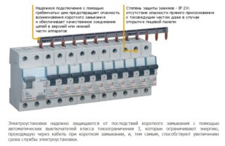
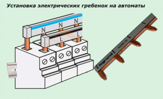
For the installation of electrical products installed in power distribution cabinets, busbars and connection bars of various types are used. A special comb for machines is one of those elements that are difficult to do without when arranging switching lines. It is used for the convenience of combining a line of automatic devices in an electrical panel, making it possible to do without hard-to-install wire jumpers.
Types of connecting bars
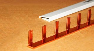
Known types of combs for circuit breakers (AB) are classified according to a number of characteristics, the main of which are:
- the total number of poles available on them;
- the number of plug-in installation modules, taking into account the fixed width;
- type of working contacts - taps or pins.
According to the first feature, the connecting bus can have several versions, among which are single-pole, double-pole, as well as 3-pole and 4-pole strips.
By the number of modules connected to the combs, they are designed for 12/24/36/48/60 seats. According to the type of contacts used in the products (this division concerns the design features of the combs), they are all divided into pin or toothed samples. The first of the varieties is of the universal type, as it is suitable for any modular machine or a similar device.
Design features

Differences in the designs of electric combs are associated with the following features of their device:
- The number of insulated plates in a comb busbar is equal to the number of its poles.
- Each type of connecting comb is used for specific purposes only.
- Single-pole connectors are used exclusively for single-phase machines, and 4-pole connectors are used for switching 3 phases and zero, for example.
The known models of combs have two designs, differing in their pitch (18 mm and 27 mm). The first is designed to connect single-module machines, the declared width of which is just 18 mm. Combs with a pitch of 27 mm allow combining devices with a housing width of 1.5 modules (18x1.5 = 27 mm).
The design of the connecting devices is designed for the installation of a large number of machines with a total number of terminals from 12 to 60. This explains why it is not advisable to use them to install 2 or 3 devices, for example. Traditionally, these ancillary products are used to assemble switchboards with a significant number of switching devices.
When familiarizing with the design of the combs, special attention is paid to the cross-section of the phase connecting bus made of copper, which should not be less than 16 sq. Mm. An approximate calculation of the amount of wire that is saved on such a replacement removes all doubts about the advisability of using these copper products.
Types of bends
There are two types of take-off contacts that are part of the connecting combs.
- Taps made in the form of pins and designated as "Pin". They are used very often as they fit most automatic devices.
- Fork branches marked with the “Fork” symbol.
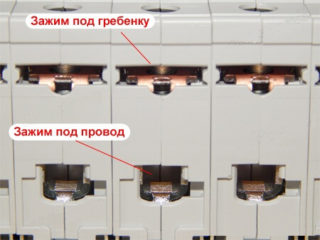
The second of the types of contacts is used much less often, since their installation will require a special clamp, which is not available for all connected AB. The cross-section of the tapping pins is selected in such a way that it is sufficient to work with load currents up to 63 Amperes inclusive.
When choosing single-phase buses, as well as any other dimensions that differ in the type of taps, you will need to take into account a number of design features. For each class of connected devices, only a specific bus pattern is suitable. When they try to install a connecting comb, the taps of which do not correspond to this device, they may simply not fully enter the slots. In this case, some part of the plane of the tires remains open, which poses a threat to users and installers.
As an example, ABB automatic machines are given, the body of which is produced in two versions: S200 and a simpler model - S200L. The first of these samples will use a PSH tire, while the S200L will require a different PS type.
Chinese dies with standard taps may not fit the pitch at all, resulting in inability to use them. Experts advise not to skimp on the quality of these products and purchase only after consultation with sales managers.
Advantages and disadvantages
- Simplicity and high speed of assembly.
- Getting a high-quality and reliable electrical connection.
- Reducing the total number of contacts by half, which increases the reliability of the resulting connections.
When installing typical jumpers made of electrical wires, there are two bare contact ends per terminal at once. When using a single-phase comb, for example, only one tooth (branch) is used.
Installation specialists solve the problem of saving contacts in their own way - they connect the machines not with separate jumpers, but with a solid wire. For this, loops with the desired bending radius are made in the areas of electrical connections.
The disadvantages of the connection method, in which electrical connecting buses are used, include:
- The inconvenience of replacing the automatic protection device, since in this case it is necessary to remove the entire comb entirely.
- The impossibility of adding another automaton (this will require its new dimension).
One of the possible solutions to the problem of the second case is to install in advance in the panel backup devices with frequently used ratings of 10 and 16 Amperes. Their output contacts are left unused until a certain point in time, and they themselves constantly remain in the off state.
Taking into account the special methods of assembling machines and their redundancy, the use of connecting combs is advisable in any situation, despite the existing disadvantages.
Connection diagrams of machines through a connecting comb
Since the combination of machines in 220 Volt networks is carried out only in phase (without zero), such a bus is usually called a phase bus.
Depending on the type of power circuit in which jumpers for machines are connected, they are calculated to work either in a single-phase line (220 Volts), or in a three-phase network. In the second case, the switching circuit is a triple copy of a single commutation. The difference between the two options is only apparent in the design of the bus connector itself.
According to the PUE, the element is designed to create reliable contact between the upper (supply) terminals of automatic devices, the voltage from the output of which enters the load line.For this, the bus must withstand significant currents, which determines the scheme for its inclusion in the general power supply circuits - all machines are connected with its help in parallel at the input. This rule is true both for single-phase (single-row) buses, and for three-phase combs for automatic machines. In the second case, a copper product has three isolated rows, shifted by a step, corresponding to the distance between the phase terminals of a 380 volt switching device.
Features and installation rules
According to the requirements of regulatory documents, the phase bus is located only on the upper contacts of the machines, combined into one line.
The peculiarities of connecting a busbar with a comb are also manifested in the following subtleties:
- Since its conductive part during installation falls between the lower pressure plate and the comb itself, the plastic insulating protrusion on it must face the screw fastening.
- If this requirement is violated, it is not possible to obtain an aesthetic joint that is devoid of plate bending.
- When installing a 3-phase type comb, it is important to monitor the correct location of the insulators, which will exclude the possibility of phase-to-phase short circuit.
In the process of installing connecting busbars for machines instead of standard wire jumpers, it is imperative to observe the generally accepted marking. It is applied to the bodies of the mounted products and must comply with the requirements of the current standards.
Typically, such combs are sold with already measured standard rulers, the number of mounting contacts on which is different. Therefore, before connecting, the total number of connected machines is calculated and, taking into account their thickness, an unnecessary part of the bus is cut off.
Connection of RCDs and differential circuit breakers
- Together with a line of several machines, one or more RCDs are installed.
- Instead of automatic machines and RCDs, differential devices that completely replace them are lined up in a line.
Difavtomat is an RCD and a conventional circuit breaker combined in one case.
The first case, in turn, involves two installation options: the comb is used in a single-phase circuit or installed in a three-phase power line.
Single-phase switching
The peculiarity of such a connection is that a single-pole ruler is required for machines, and a two-pole for an RCD. The condition for the operation of the latter is the joint commutation of the phase and zero. In this case, they proceed from the principle of maximum possibilities, that is, they choose a two-pole bus, and the ground taps falling on the machines are simply folded back.
3-phase connection
In this case, you will have to use a 4-pole comb made of copper, the three phase contacts of which are used both on the machines and on the RCD. The fourth "zero" row is used to connect to the RCD, and in the area of the "earth" contacts of conventional disconnecting devices, it is simply folded back. When installing some difavtomats in any situation, the taps of the comb are connected to all contacts used in the circuit.
A connecting comb for circuit breakers and RCDs is a convenient way to combine them into a single structural unit.It can be used both in standard closed-type distribution cabinets and in any other place designated for the installation of switching devices.


