A relay is a system of switches needed to switch, disconnect and connect electrical circuits. The purpose of operating a switching device is to create specific operating conditions for equipment. Connecting a relay means putting a load on the switch that controls the device.
- Relay mechanisms
- Principle of operation
- Varieties of relays
- Number of phases
- Switch type
- Type of activation of the perceiving element
- Load control type
- Signal arrival type
- Contact features
- Normally open
- Normally closed
- Crossover
- Relay wiring diagram
- Connection diagrams
- With multiple contacts
- For voltage relay
- Relay settings
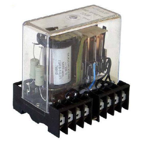
Relay mechanisms
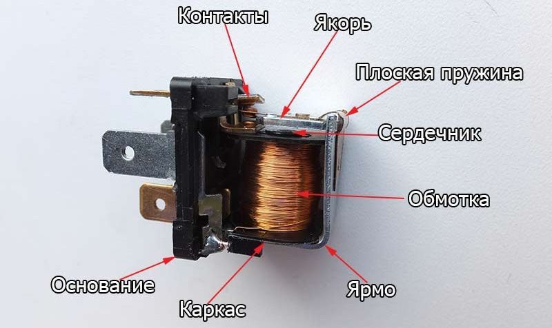
The relay device is made in the form of a coil entwined with a large amount of copper wire. Inside it is a core-rod made of metal, fixed on the yoke - an L-shaped plate. On top of the core and coil is an anchor - a metal plate that is held by a return spring. Moving contacts are attached to the anchor, and stationary contacts opposite them.
The coil and core assembly is an electromagnet, and the core, armature and bright assembly is a magnetic circuit. Contacts provide control of the electrical circuit, opening and closing it.
Principle of operation
The principle of operation of the relay of the 4-pin or 12-volt model is similar. Without applying voltage to the device, the armature is remote from the core by means of a return spring.
At the moment when the voltage is applied, a current begins to move through the winding, the magnetic field of which acts on the core. The magnetized element, by overcoming the forces of the return spring, attracts the anchor. Its active contacts move, opening or closing with fixed ones.
After the voltage supply is interrupted, the winding current disappears, and the core demagnetizes. The return spring brings the armature and contacts to their original state.
Varieties of relays

Relay devices are classified according to several parameters.
Number of phases
Subdivided into:
- single-phase - designed to supply voltage in residential premises;
- three-phase - suitable for use in industrial environments.
Three-phase devices turn off the power of all equipment in case of voltage surges on one of the lines.
Switch type
You can purchase models:
- maximum - increase the voltage parameter to a certain value;
- minimum - decrease the indicator to the specified value.
The voltage threshold is not set by the user.
Type of activation of the perceiving element
The perceiving element, by switching on which the device will work, is an electromagnet, a magnetoelectric unit, an induction or electrodynamic system. Depending on its type, there are relays:
- primary with direct connection of contacts to the network;
- secondary - can be connected via measuring inductive or capacitive transformers;
- intermediate - amplify or transform signals of primary / secondary models.
The functions of the receiving element are the transformation of voltage into the process of movement of the armature relative to the yoke.
Load control type
The following models are used to control voltage:
- direct action - the load is switched by contacts;
- indirect action - secondary elements are connected to the load.
The load is applied and suspended at regular intervals.
Signal arrival type
The following switching devices can be found on sale:
- electronic - provide voltage control under high load conditions. Control lighting and vehicle components;
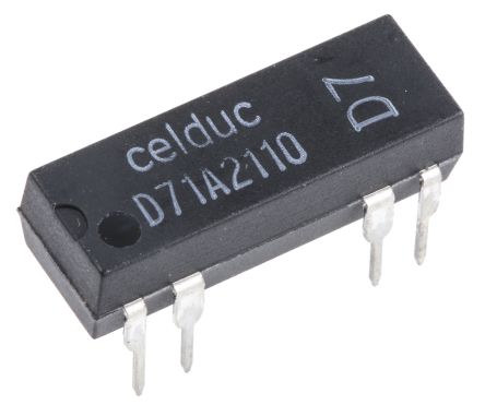
- reed - small models in the form of a coil. Designed for closing, switching, opening the network. Sensitive to mechanical stress and ultrasound;
- electrothermal - turn off and turn on the electric current by heating the bimetallic plate. Used for electric motors in production, arrangement of a single-phase or three-phase power grid;
- time delay - deceleration schemes are used to create short-term pauses. Devices work in cars, traffic lights, Christmas tree garlands;
- light timers - allow you to program the lighting of greenhouses, aquariums, livestock complexes. Heaters, fans are connected to them;
- electromagnetic - the static winding current is activated by the influence of a magnetic field. Devices with an average load of up to 320 A and a voltage of up to 1.6 kW can only be operated on a direct current network.
Structurally, the standard regulator looks like a bag for mounting on a DIN rail. Some models are made in the form of adapters and extension cords.
Contact features
By design, the contact intermediate relay consists of three types of elements.
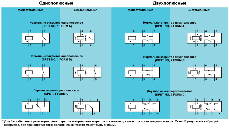
Normally open
They are in the open state until the coil is energized. The relay is activated after energizing and the contacts come into closed state. The power grid is being closed.
Normally closed
They function according to the opposite principle, being in a closed state at the moment of relay de-energization. After the appearance of voltage, the relay is triggered, the contacts and the circuit are opened.
Crossover
When the coil is de-energized, the middle common contact of the armature is closed with the fixed one. After the relay is triggered, the middle element, together with the armature, moves in the direction of the stationary contact and closes with it. The connection with the first stationary contact is broken.
Models with multiple contact groups provide control of multiple circuits.
Relay wiring diagram
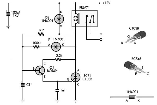
The schematic diagram of the relay is applied to the cover by the manufacturer. The device itself has the form of a rectangle, marked with a marker K with a number. To designate contacts without a load, the letter K is used with two numbers separated by a dot. The first is the serial number of the device, the second is the serial number of the contacts.
Contact groups next to the coil are marked with a dashed line. The parameters of the contacts, the value of the maximum switching current, are also indicated under the wiring diagram. A variety of currents and voltages under operating conditions are applied to the relay coil.
Connection diagrams
The module is connected to consumers depending on the design and the number of contacts.
With multiple contacts
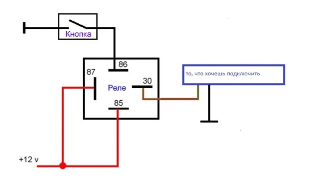
Light relay activation and operation circuit, consisting of 4 pins allows you to connect fog lights through a fuse:
- Finding additional voltage by cutting the red wire on the safety block and soldering the additional one.
- Installing a fuse.
- Connecting the power relay by contact numbering. 30 - cable after the fuse, 87 - cable to PTF directly, 86 - wire with a bolt hook near the relay.
- Creation of a control system. The PTF button is pulled out without removing the pads.
- Testing the wire with a multimeter and connecting it to the body.
- Checking headlights and dimensions.
- Repeated dialing with a multimeter and searching for the digit 12+.
Contact 85 is thrown only on the wire, when touched, 12+ appeared.
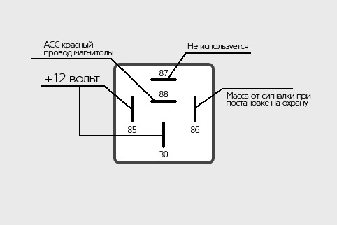
Connection diagram five-pin the relay is suitable for generating an alarm. The connection is done like this:
- Definition of contacts.85 and 86 are responsible for the coil, 30 is common, 87 is normally closed, 87 is normally open.
- Supply terminal 85 is connected to the signal wire.
- Coil contact 86 is supplied with 12+ volts when the ignition is on.
- Contacts 87-a and 30 are thrown into the open circuit of the blocked circuit.
- Polarity is inverted. Coil contact 85 and contact 87 are minus, and contact 86 from limit switches is plus. On the 30th, there is a plus.
A gasoline pump, starter, injector power supply, ignition can be used as a blocker.
For voltage relay
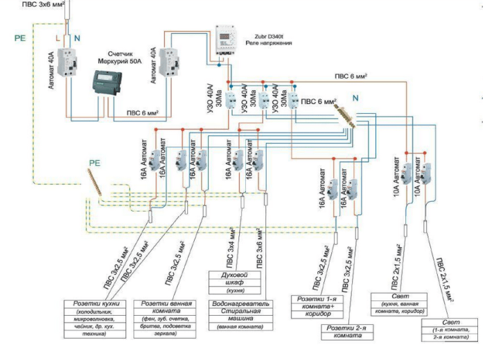
The voltage relay connection diagram provides for the installation of the device on a DIN rail in the switchboard. For a three-phase network, the following is done:
- The connection cable is determined - copper, with a cross section of 1.5-2.5 mm2.
- The input contacts are connected via a starter or contactor.
- The phase is located by markers A, B, C and the zero terminal N.
- The conductors of the three phases are thrown onto the corresponding upper terminals of the device.
- Terminal # 1 conductor connects to coil output.
- Terminal No. 3 is connected to a phase bypassing the voltage relay.
- Output No. 2 of the contactor coil must be connected to the neutral conductor of the network.
- The load conductors are connected to the output terminals of the starter.
- Neutral conductors in the switch box are thrown to the common neutral.
For ease of connection of units, refer to the diagram on the relay case.
Relay settings
The circuit for turning on any relay will only work when properly configured. The user can set the threshold for the maximum and minimum value, select the delay of activation and re-inclusion after reboot.
Having decided on the type of switching relay and understanding its circuit, you can create an electrical circuit yourself. When working, you should take into account the type of contacts, the type of device and the principle of its functioning.