The technical solutions of modern houses are replete with devices that create a load on the network. Electric hobs, ovens, boilers and boilers are leading in consumption. The demands of modern induction cookers reach 11,000 VA, and the metering equipment is not connected directly at 100+ A. An alternative choice is to use current transformers (CTs) for electricity meters.
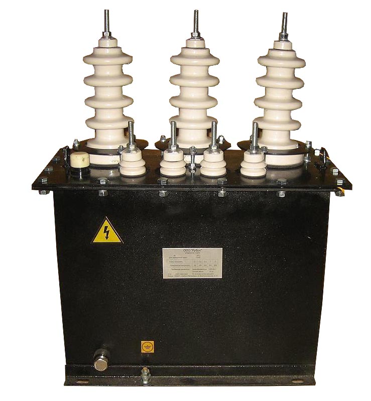
TT device
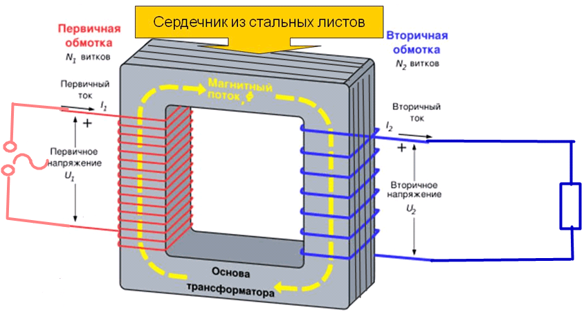
Transformers convert the measured value from larger to smaller or vice versa. They work by means of electromagnetic induction. The device is based on a magnetic core, assembled from rectangular steel frames, and on it are fixed turns of insulated wires - windings. The input coil is connected to the source and the TT is represented by only one turn. Depending on the transformer model, the place of the primary winding can be occupied by:
- core winding;
- a fixed busbar with a connecting screw that passes through the housing;
- a stepped or rectangular hole to pass and secure the bus during installation;
- round window for cable conductor for contactless connections (household relays with built-in transformers).
The difference between instrument transformers and power transformers is that the secondary circuit current remains constant regardless of the consumer's resistance - the voltage changes. When the current transformer is connected to the mains, the secondary winding must not be opened. It must always be short-circuited to the measuring device, in its absence - short-circuited by jumpers. If the generated current disappears, the voltage reaches the value in kilovolts. A jump will provoke a failure of the equipment (semiconductor devices are especially sensitive), damage to the insulation and fire, a turn circuit, and injury to the maintenance personnel. For safety reasons, grounding of each winding at one point is mandatory.
Key parameters of instrument transformers
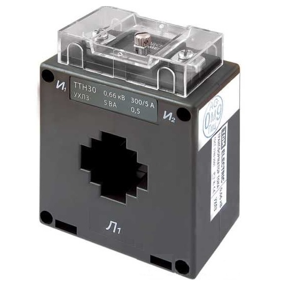
The rated voltage determines the circuits in which the transformer can function. There are two large groups: up to 1kV and above. In everyday life, converters of the 0.66 kV class are common.
The transformation ratio is the ratio of the rated primary and secondary currents. At the input, the values vary depending on the parameters of the supply network: 1, 2, 5, 10, 15, 20, 30, 40, 50, 75, 80, 100, 150, 200, 300, 400, 500, 600, 750, 800 , 1000, 1200, 1500, 1600, 2000, 3000, 4000, 5000, 6000. At the output, it is unified under the scale of measuring instruments 1, 2, 5. The marking with the designation looks like a fraction (50/5, 100/5, 200 / 5, etc.).
The accuracy class indicates the maximum permissible error in energy accounting as a percentage. The most accurate instruments are used commercially:
- 0.2s;
- 0.5s.
The s symbol indicates that accounting is possible within the minimum division. For other models, this is a blind spot.
In measuring circuits of different directions:
- 0,1;
- 0,2;
- 0,5;
- 1;
- 3.
Relay protection: 10P.
If the number of windings is more than one, the accuracy class is determined separately for each. Up to 1000 V, it is customary to connect simple CTs in series, and above 1000 V it is costly, therefore, one converter with several windings is installed. For example, the first can be on the protection circuit - 10P, the second 0.5, the third - 0.5s.
Failure to comply with the rated load power specified in the characteristics of the transformer (5 VA, 10 VA, 15 VA, 30 VA, etc.), the accuracy class falls relative to the declared one.
Accounting node equipment
For the accounting cabinet of a node over 100 A, a minimum set of equipment has been determined.
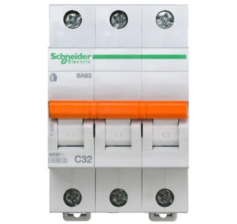
Input circuit breakerthrough which the power line enters the internal network. From its bottom to the transformers, access for unqualified personnel is closed according to regulations. A simple version of protection is represented by plexiglass, fixed with sealed pins.
Current transformers... The transformation ratio depends on the power that is allocated to the network user. The calculation is made by Energosbyt employees and provided with technical specifications (technical specifications).
A single-phase meter does not require the use of converters. In three-phase networks, the load distribution can be uneven, therefore, accounting is carried out for each phase separately. It is necessary to select all 3 TTs from one manufacturer, with the same set of properties.
The technical passports must be kept before registering the site. The inspector will not accept a transformer after the release of which more than a year has passed. There is a special plug with a screw for the seal on the device case. Under it can be a second pair of grounding clamps and a fixture for the voltage network.
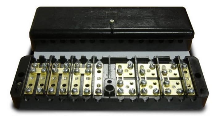
Terminal block measuring KKI (test panel) consists of 2 sectors. The current one has 7 pairs of terminals. 1 - grounding. The 6 others are suitable for the wires from the secondary windings of the TT. Between them, you can install pairwise jumpers to close the network before disconnecting the accounting device. Phase A, B, C cables and neutral conductor N enter the voltage sector. Slide jumpers allow you to open the circuit with a screwdriver.
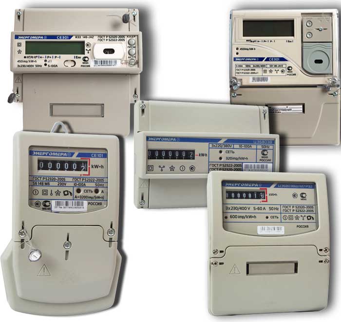
Counters can be electromechanical (disk), electronic (with LCD display, remote control), combined. Energosbyt prescribes the requirements for the device in the technical specifications individually. The connection diagram for each model is on the cover or in the attached passport.
The universal meter has 10 terminals, grouped by 3 for each phase, the last one being zero. The first, third terminal is the output from the secondary winding of the transformer I1, I2; the second is a phase wire.
Manufacturers produce similar meters with direct and no connection. When selecting, you need to carefully study the marking. On the phase meter, instead of the maximum permissible current value, the transformation ratio is indicated (for example: 5 (7.5), 3X150 / 5 A)
Wires use rigid, cross-section 2.5+ mm2, forming rings for connection. Soft with insulated tips available. In the meter, the core is clamped with two screws.
Cartridge with an electric lamp through a key switch against condensation in outdoor panels.
Boxing with windows for the meter display and machine levers.
The complete set is supplemented with protective automatics in accordance with the power grid project.
To select a transformer for a three-phase meter, you should draw up the desired wiring plan for the power grid, approve it with a regional representative of Energosbyt and obtain technical specifications. The model should be chosen strictly according to the characteristics specified in the document.