In modern wiring, radically new elements are often used. One of these is an impulse relay (IR). The mechanism allows you to easily control lighting from several places at once, which is especially convenient for long extended rooms or a courtyard. You can also put a simple one-button switch for several lighting fixtures in the room at once.
Device and principle of operation of IR
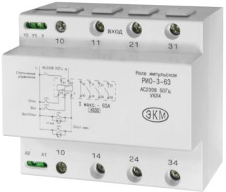
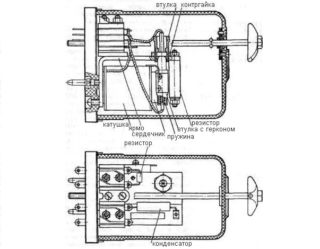
Structurally, the relays consist of the following blocks:
- Coil. It is a thin copper wire that is wound around a non-magnetic material that does not allow electricity to pass through. It can be fabric or varnish.
- Core. It comes into motion at the moment the current passes through the winding of the coil due to the fact that it contains iron.
- Anchor (movable). It has the form of a plate that affects the closing contacts.
- Circuit status switch. It is also called the contact system.
The action of IR is entirely based on such a physical phenomenon as electromagnetic force. The principle of operation of the relay is stepwise:
- When the IR is switched on, a current flows through the coil core.
- As a result, the core, attracting it, simultaneously brings into operation all power contacts. Moreover, they are normally open or closed.
IR is a kind of mechanism that breaks or closes an electrical circuit. Sometimes a resistor, semiconductor diode or capacitor is connected to the device for more accurate operation.
IR varieties
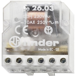
All lighting control relays are divided into two groups:
- Electromechanical. The mechanism is responsible for the action of the device.
- Electronic. The brain of an IR is a printed circuit board equipped with a microcontroller.
All types of impulse relays are characterized by the following features:
- The output current is its maximum indicator for the coil clamps at the time of the armature exit.
- Retraction current. Its lower value when returning the working anchor to its original position.
- The coefficient is returnable. The ratio of the output currents to the pull-in current.
- The magnitude of the trigger. This is the optimum value of the input signal to which the impulse switch reacts.
- Setting. The parameter of the mechanism triggering within certain limits set in the relay.
- Nominal values. All indicators of current, voltage, ensuring the operation of the device.
- Response time. The duration of the response to the given command. It can vary from 0.0001 sec. up to 1 min.
Electromechanical devices are more popular.
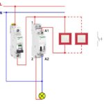
Relay connection diagram with one normally open contact
The relay-switch can be connected according to one of the simplest schemes. This greatly facilitates the work of the wizard. The main thing to remember: the switch responsible for the lighting process should only be in the open state. This is due to the fact that it has an opening spring, which is instantly triggered at the moment the button is pressed. As a result, the circuit closes in a different place.
The connection is performed as follows:
- one contact output is connected to the phase;
- the other goes to zero;
- the neutral wire is pulled to each lamp used in the lighting.
It is forbidden to exceed the permissible number of switches specified in the passport for the relay. If you ignore this, the device can often falsely trigger.
To prevent the device from sparking at the moment of switching on, it is advisable to install a capacitor as well. After completing the installation of an impulse relay for controlling lighting, they make full isolation of the contacts. For this, it is better to use special heat-shrinkable cambric.
Advantages and disadvantages
If we consider the pros and cons of impulse relays, this must be done for each type separately. Electromechanical switches have the following advantages:
- Favorable cost in comparison with electronic ones.
- Powerful 5 kV isolation between the contact block and the winding coil.
- A weak voltage drop across the off contacts, which means a low percentage of heating of the device.
- Inertia to overvoltage surges and disturbances arising during lightning.
- Possibility to control a line with an optimal load up to 0.4 kV.
Among the disadvantages of electromechanical impulse light switches are:
- Radio interference when the circuit is turned on and off. To avoid this effect, it is necessary to resort to shielding, or to increase the distance from the relay to devices exposed to external waves.
- Relatively rapid wear of the switch at high voltages and currents. It includes deformation of springs, oxidation of contacts.
- Longer response times than circuit-breakers with a board.
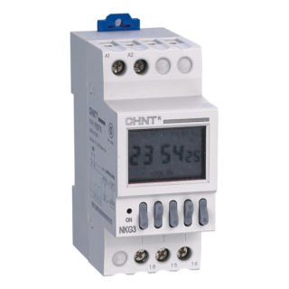
The following advantages are characteristic of electronic pass-through relays:
- excellent switching speed;
- good security for the master and users;
- wide range of models;
- acceptable cost;
- the presence of indicators that notify about the mode of operation of the device;
- silent operation;
- extended range of possibilities.
Electronic relays can be mounted in different ways - on the DIN-rail of the shield or directly into the socket.
The disadvantages of devices are:
- strong overheating to a critical point, provided that a large current is switched;
- disruption of work at the slightest network failures;
- frequent "glitches" with impulses for no reason in the opinion of the master;
- the presence of high resistance in the closed position;
- disconnection of the relay if a short-term voltage drop has occurred in the network;
- the ability to operate some types of devices only with direct current;
- delayed passage of current opposite to the usual direction due to the peculiarities of the semiconductor circuit.
Despite the fact that electronic controlled switches have a greater number of disadvantages, the devices are constantly being modified and improved. Therefore, it is possible that they will soon replace electromechanical relays completely.
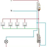
How to avoid mistakes at 3 levels when connecting the IR to the electrical panel
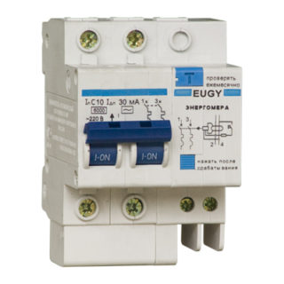
For a master with no experience, the task of connecting a relay becomes quite difficult. The specialist is often lost in determining the sequence of connecting elements with each other. Moreover, the more switches used, the more difficult the work will be. The simplest is the installation of a relay to a one-key element.
In fact, the work is not as difficult as it seems. The main thing is to comply with all installation requirements, then the number of relay control buttons can be unlimited.
If there are three levels of connection, step-by-step installation should be performed.
- Installation of RCDs to protect lighting.
- Installation of the machine for several groups of backlight sources at once.
- Installation of an impulse relay.
RCDs are assembled according to a typical scheme for an electrical panel and meter. Then it is worth installing and connecting the protection machines for individual groups. They work for control cables and all luminaires. Then the relay is mounted. Moreover, it must be remembered that they put their own IR on a separate group of lighting devices.
If you do all the work in the given sequence, it will be possible to control light sources inside one room using a one-key automatic switch, instead of a multi-key one. This keeps the user from getting confused about the buttons.
When working with an electric meter, IR and other network elements, it is advisable to do everything with rubberized gloves and be sure to de-energize the line.

