Most modern household appliances made using inductive elements are easily adjustable for power consumption. True, this is true only for those cases when such a possibility is already provided for. However, even in its absence, you can modify the device with your own hands by integrating a triac voltage regulator in an inductive load into it.
Advantages and disadvantages
There are voltage regulators on the market, built on the basis of modern BT136 600E triacs, which significantly surpass thyristor counterparts in their performance. The use of bidirectional control semiconductors provides the following advantages:
- reduction of nonlinear distortion;
- improving the control characteristics of the entire circuit;
- small savings in electricity consumption.
The main advantage of any electronic controllers is the absence of mechanical contacts, which quickly fail and create a lot of noise.
Not very significant disadvantages of these devices include:
- increased sensitivity to transients in control circuits;
- the need to install a radiator to remove heat;
- limited frequency range.
Despite all these disadvantages, triac stabilizers are successfully used to regulate power in an inductive load.
Principle of operation and purpose of application
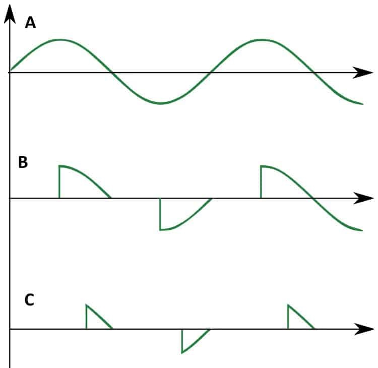
The principle of operation of a triac regulator is based on the features of semiconductor devices, which limit the amplitude of the alternating current while reducing the power in the load. At a given frequency of the mains voltage, it is possible to regulate this indicator within small limits (no more than 20-30%).
The quality and depth of adjustment depend on the control circuit for the operation of the triac elements, which assumes different designs.
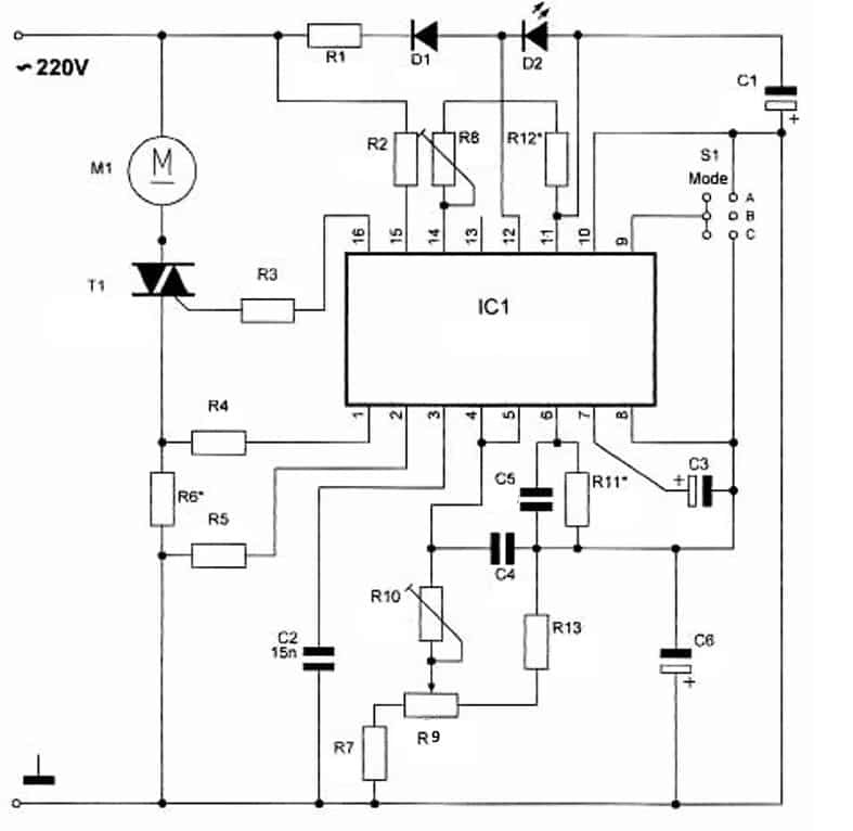
In the simplest cases, it consists of several discrete elements: diodes, an isolation transformer, resistors, and capacitors. In more complex devices, the function of the regulating module is performed by a microcircuit or microprocessor. In accordance with the method of triac control, various methods of changing the amount of power supplied to the load are possible. The most common way to do this effectively, with minimal losses, is to influence the phase of the converted voltage. In accordance with the variable parameter, this method is called pulse-phase, and the device operating on its basis is a phase power regulator.
Triac circuits are used in many devices, when working with which one has to deal with an inductive load - electric motor windings, in particular. The same category of industrial and household appliances includes:
- washing machines, hair dryers, and compressor units;
- boilers, vacuum cleaners and a number of models of lighting devices;
- pumps and asynchronous electric motors of factory machines;
- boiler equipment and even ordinary soldering irons.
The nature of the use of equipment controlled by phase power regulators on triacs is practically the same. Only the performance indicators of the semiconductor devices themselves differ: the magnitude of the current, the power in the load, the control efficiency, the economy, and others.
Self-production
Anyone who has mastered the principle of its operation can make a voltage regulator on triacs with their own hands. To do this, you first need to select a branded device option suitable for manual copying. One of the conditions for making the right choice is that the scheme you like turns out to be simple enough to repeat.
Scheme options
Among the popular models of industrial devices that can be taken as a sample, the following stand out:
- Products built on the basis of BT136 600E devices, the voltage regulation circuit of which is available on the Internet.
- Devices based on BTA16-600 triacs with a more complex switching organization.
A feature of the first circuit solution is the use of only one triac. By means of such a regulator, repeated in the form of a homemade product, it is possible to control the operating modes of a household soldering iron with a power of up to 0.09 kW. In addition, if you have a device, you can adjust the brightness of a desk lamp or the rotation speed of an electric fan.
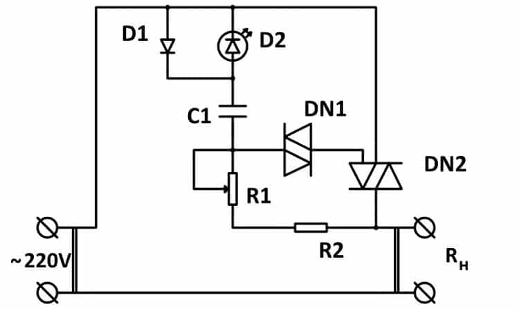
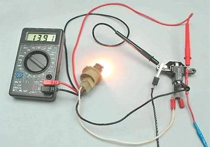
Among the circuit solutions used for the independent manufacture of the regulator, a product based on relatively powerful semiconductor devices BTA16-600 stands out. Its characteristic feature is the presence of a neon lamp included in the output circuit. The brightness of its glow indicates the amount of power supplied to the load at the moment, which is very convenient for working with many consumers.
A user who has no experience with microcircuits will have to use the combined option. The control unit is taken from a simpler product based on the BT136-600E, and the output uses a control circuit with a neon lamp. In a situation where the regulator is intended to control an illuminator with its own internal starting element (starter), it is allowed not to install the neon.
Another variant of the proprietary repeater device is possible, which uses the MAC 97A6 controls. This switching circuit is suitable for 220V lamps.
Self assembly
The structure of a typical regulator circuit on triacs includes the following mandatory components and elements:
- rectifier diodes (or bridge);
- an adjusting resistor, the knob of which is displayed on the front panel of a homemade device;
- limiting dinistor of any type;
- triac BTA16-000;
- indicator LED instead of neon;
- fuse.
After all these parts are soldered into the circuit, you will need to check the order of operation of each of the individual modules. To do this, you need to walk the entire chain from the entrance to the load.
The AC voltage of 220 volts rectified by diodes is fed through an adjusting resistor first to the limiting element, and then to the control electrode BTA16-000. Depending on the position of the potentiometer knob, the triac will open more or less, changing the amount of power supplied to the load. According to this description, the assembled circuit is checked for the correctness of its assembly and operation.
By means of such a simple regulator, it is possible to smoothly change the output power of a soldering iron or a table lamp, for example.
Regulator setting
After completing the soldering work and all the necessary connections, you can proceed to check the homemade product for operability. If deviations from the normal modes specified by the description of the circuit design are detected, the device will need to be configured. It consists in checking each of the elements for current and voltage. For this, it is most convenient to stock up on a special device - a multimeter, or even better - an electronic oscilloscope.
Before making the adjustment, it is important to remember that the triac in this circuit performs the function of a phase regulator.Its main purpose is to switch the circuit at the moment of the transition of the half-wave voltage to the zero point, taking into account the magnitude of the load being operated at a given time.
In the initial state, the triac is closed, since the voltage at its control electrode has not reached the desired value. As the capacitor is charged through the circuit, which opened due to the arrival of a half-wave of voltage, the potential on it and on the dinistor connected in parallel gradually increases.
These processes are clearly visible on the oscilloscope screen, in the presence of which the device setup will be noticeably simplified.
When the voltage at this point reaches a value of about 30 volts, the dinistor and triac simultaneously open for a time equal to the half-period of the wave. Due to the switching of the control circuit, periodically repeating at a frequency of 50 Hertz, it is possible to change the amount of power in the load within the specified limits.
If you have experience with a soldering iron and electronic devices, it is possible to assemble and configure the control device without much difficulty. The main thing is attentiveness and strict adherence to the instructions given.


Very bad!
The title and content of the article have nothing in common ((
To work with an inductive load, the circuit must be more complicated - contain a snubber,
otherwise, "magic smoke" comes out of the triac and it stops working ((
The article is not gamot. From the first words - an obligatory element of a diode or a rectifier is nonsense. This is necessary for a thyristor regulator. Triac does not need it.
Well, for an inductive load, the circuit, as already mentioned, is somewhat more complicated.
In datasheets for triacs, all the details are available.
Why has there been so many articles recently written by completely incompetent people. It's so fashionable to express yourself. The main thing is to write or rewrite and that's it.