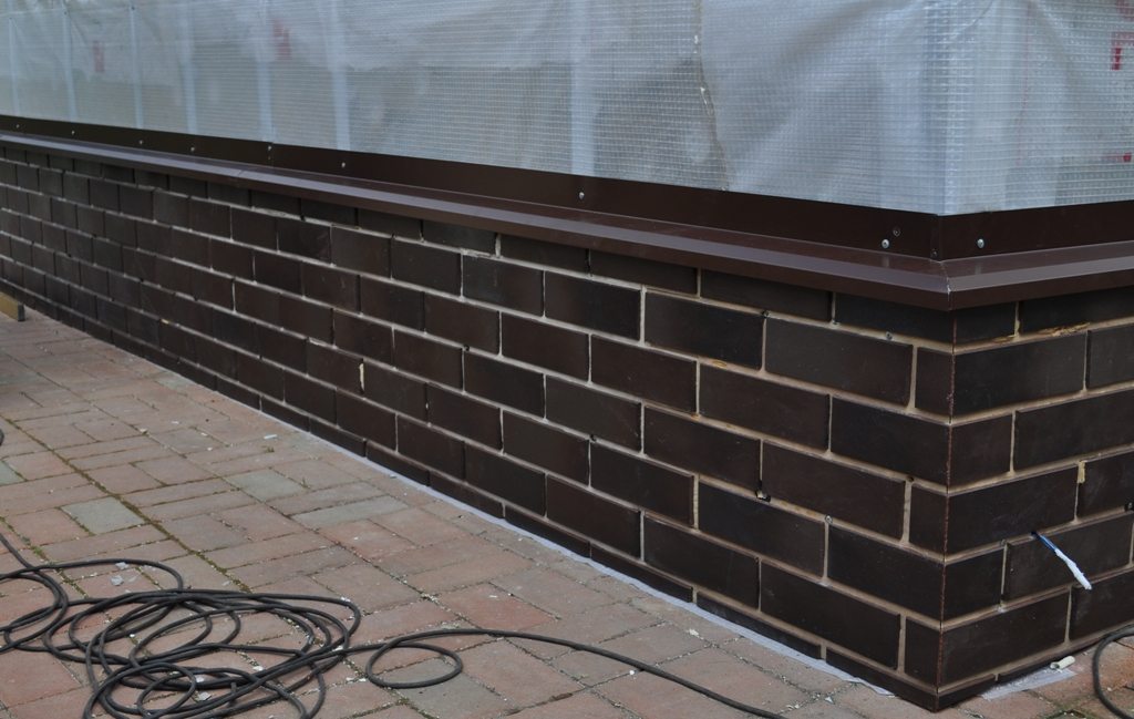
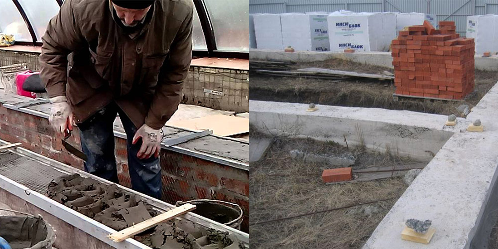
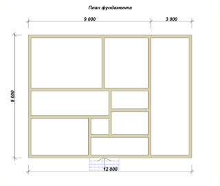
The foundation drawing contains a plan for placing monolithic sections or prefabricated blocks with reference to the axes of the building. The reliability and quality of construction, the accuracy of transferring dimensions to the terrain depend on the scheme. The foundation plan is drawn to scale, indicating the geometrical dimensions and deepening marks. Surveyors make markings on the construction site; they use a level and a theodolite in their work.
Nuances in the construction of the foundation
The foundation accumulates the loads from the structure and transfers them to the ground under the sole. The soil perceives forces and deformations from stresses appear in it if the design resistance of the layers is less than the applied load.
Sometimes the increase in the sole does not help withstand the pressure, such soils are called weak. Unstable soils are used for construction after increasing the bearing capacity as a result of processing by special methods.
The plan of the future foundation is drawn up after the main drawing of the structure. Supports are provided under the walls, additional sections are made for columns, vertical elements, so the contour in the plan can be of various shapes.
The foundation under the extension is designed taking into account the binding to the base of the house. Support for pillars or columns is arranged for each construct separately or in the form of ribbons for several elements at once.
The need for a plan
The foundation project for the house must meet the requirements:
- contain simple technical solutions that are convenient to execute on the ground;
- provide for the construction of advanced construction methods with savings in labor and materials;
- include in the composition durable structures that do not tip over and do not slip in the ground;
- contain the required dimensions tied to the axes of the walls of the house.
Material costs for the construction of the foundation are 10% of the total cost of the building in the absence of a basement and 15% in the case of using a basement. Labor intensity of work is 12 - 15% of the indicator for the entire building.
Basic calculation parameters

The support of the house is designed according to calculations that are performed on the basis of engineering and geological studies.
The following data are taken into account when choosing a foundation layout:
- design features and purpose of the house, the amount of pressure on the base;
- the mark of the laying of adjoining supports and the laying of adjacent communications;
- the relief of the built-up area;
- mechanical and physical properties of the earth, overlapping layers, the presence of areas of weathering, etc.;
- the impact of construction on changing soil characteristics;
- the likelihood of soil erosion during construction in water bodies;
- the depth of freezing of the earth and the height of the standing of soil fluids.
A reasonable depth mark is selected after comparing several alternatives.The markup in the plan is performed along the auxiliary and main axes of the structure, while the elements are detailed, a drawing of the foundation section is drawn up.
Features of building a foundation plan
Monolithic, prefabricated sections and their parts are given symbols that include the type of product, size and other information. Requirements for diagrams and drawings are regulated by GOST 21.101 - 1979, while taking into account the requests of ST, ESKD, CMEA, SPDS and other construction standards.
The drawing of the foundation is carried out in a minimal volume, but so that there is enough information for the installation of prefabricated parts and the manufacture of monolithic plots. The scale is used depending on the complexity of the scheme, while the drawings of the projects of the foundations of private houses should be convenient for ordinary users.
Diagrams, drawings and explanations for the project are placed on standard sheets of paper so that it is convenient to read, reproduce and use them at the construction site. The names of the plots are made short, used in the nominative case, in the first place they put a noun, for example, a tape foundation.
Planning different types of foundations
Powerful buildings require a solid foundation and reinforced concrete belts, monolithic slabs or pile-grillage foundations are arranged for them. The level of soil water affects the heaving of the earth and determines the type of foundation.
The base is planned so that after getting wet in the soil there are no shifts and slips, on which the integrity of the house depends. In swelling soils, the foundation is laid 10 - 20 cm below the freezing mark, and in stable soils the level of freezing is not particularly important. In prefabricated bases, the size of the foundation is taken as a multiple of the height of the reinforced concrete block.
Tape
A reinforced concrete strip runs under the load-bearing walls of the house, columns and pillars. They use brick, reinforced concrete, concrete and rubble stone. The strip base has a high bearing capacity and is used for the construction of large houses.
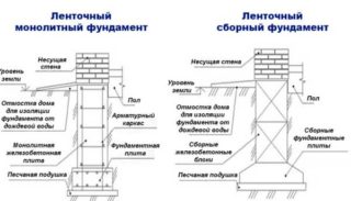
Monolithic structures are made by pouring concrete into a removable formwork or non-removable shell. The strip foundation plan drawing provides for the location of the formwork elements for the precise placement of the monolithic sections. The diameter of the reinforcement used must be indicated, and a plan for the location of the rods in the frame is given.
Prefabricated elements are prepared in factories, and in the conditions of the construction site they are laid in the design position. The belt consists of main blocks and foundation pads in the form of a trapezoid. The strip precast foundation plan contains an indication of the height of the filling of gravel, sand or crushed stone under the base of the precast element.
Pile
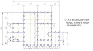
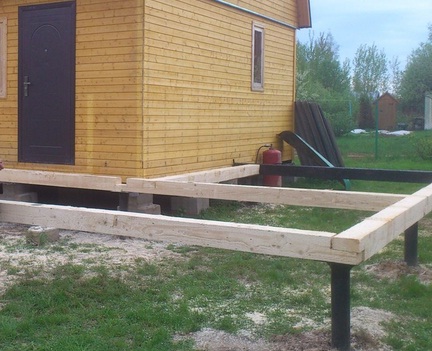
Round, rectangular or composite rods are immersed in the ground, piles are metal, concrete, wooden. The drawing indicates the groups of piles and their location in the plan with reference to the axes of the structure. On the diagram, place the position of the grillage in the form of a slab or beam for tying vertical supports.
The pile plan helps:
- clearly establish the location of the rods on the ground;
- maintain distances between vertical elements;
- determine the volume of concrete for the installation of the grillage;
- install the pile heads in the design position for subsequent connection with the piping.
Grillages are high when their soles are above the surface and low when they are buried in the ground. Raised types are made in the event of an increase in the level of groundwater or when constructing an underground. For any type, the layout of the elements in the plan is drawn and the location in height is indicated.
Platen
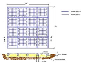
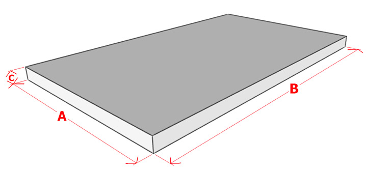
A monolithic base with reinforcement meshes is used on watered soils, often this is how the foundations of industrial buildings with a large load are arranged. In home construction, an insulated version is used, like a Swedish solid slab with insulation from the cold.
The slab foundation plan provides for:
- drawing of the pit indicating the thickness of the vegetation layer, marks for cleaning the bottom to the design depth;
- the design of removable formwork with the calculation of shields and supports;
- dimensions by thickness of reinforcing bedding made of sand or crushed stone;
- calculation of non-removable insulation elements;
- a diagram of the frame of the meshes and reinforcing ribs with recommendations for the choice of reinforcement;
- calculation of the amount of material for all structural parts of the slab.
The monolithic base is reinforced with two nets, which are placed in the lower and upper layers of concrete. Links and frames are provided between the flat elements for support.
Dependence on the size of the structure
Designers calculate the parameters of the foundation, while taking into account various conditions of influence. The size of the house and its functionality are fundamental factors in choosing the type of support and its dimensions. For industrial facilities, a strong foundation is chosen that can evenly transfer pressure to the ground from equipment vibration, shocks and electromagnetic vibrations.
If the soil under the house is weak, it is reinforced to reduce the amount of materials for the foundation of the house. The project provides for a system for removing soil moisture from the underground part and waterproofing shells. The protective layers are shown in the drawing, materials and volumes are informed in the explanatory note.
Conditions for the exact transfer of the plan to the terrain
The main parts of the drawing are made on the same scale, but individual detailing units are drawn in an enlarged form for the best reading. General scaling is performed at 1: 100, 1: 200, 1: 300 and smaller.
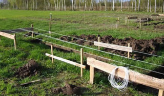
For the transfer, the axes of the structure are broken down on the ground. The surveyor maintains right angles and line spacing. The directions of the axes are marked with a cord, the marking points are set out at such a distance that will not be affected when digging trenches.
The depth of the laying is set with a level, while on adjacent walls, buildings or pillars a mark of ± 0.00 is placed, which serves as a guide for further calculations in height.


