In order for the sewage system to work smoothly, it must be equipped in compliance with sanitary and building standards. When installing highways in a private house, it is important to take into account the distances between well structures used to check, repair and clean the system.
Types of sewer mines
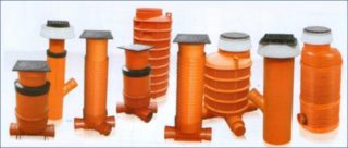
Sewer well structures are classified depending on their purpose.
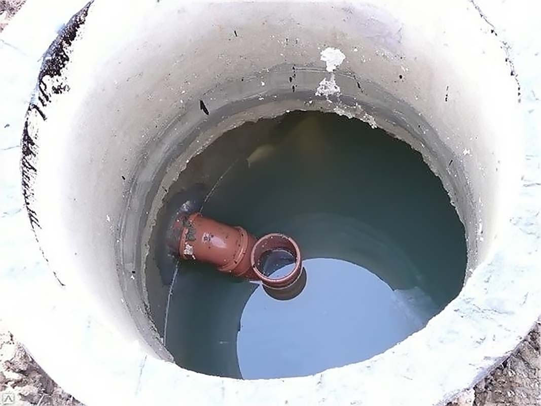
- Lookout. They are equipped to control the operation of system elements and to clean up when congestion occurs.
- Swivel. They allow you to control the areas through which the waste fluids change the direction of movement, make the places of turns and kinks more accessible, where blockages are often formed.
- Differential. They are constructed to compensate for the slope of the pipeline, since its increase or decrease leads to the settling of solid impurities in the pipes.
- Nodal. Provide access to connecting pipes.
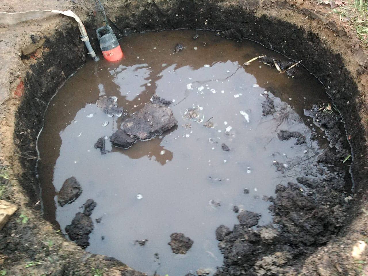
Reinforced concrete is usually used as a material for arranging inspection wells, but recently plastic tanks are gaining popularity. Any sewerage shafts are equipped underground. They play the role of connecting elements of the sewer main.
Allowable distance between manholes
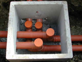
The main document that determines the features of the structures of wells in the drainage system and the standard distances between them is SNiP 2.04.03-85. It is necessary to adhere to the data specified in it when laying the sewage main in order to improve the quality of the treatment plants and ensure correct installation. If the standards are observed, cracks and leaks are not formed in structures, and sewage fluids move without obstacles. Each type of well element has its own requirements.
Inspection or revision designs
Wells are equipped when installing a pipeline of considerable length, with many turns and bends, where there are branches and transition elements with a change in the pipe section.
The maximum distance between inspection units is determined depending on the section of the pipe sections used for assembly:
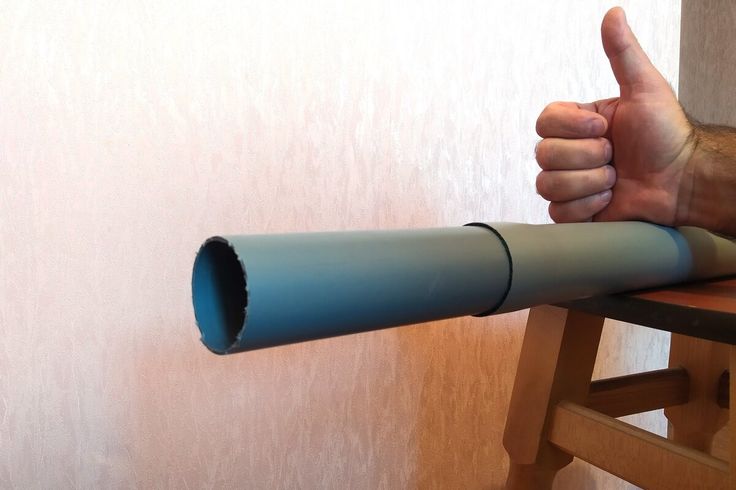
- With a line diameter of 100 mm, well structures are equipped at least after 15 m.
- If the cross-section of pipes is 150 mm, then the distance increases to 35 m.
- With a pipeline size of 200–450 mm, the revisions are mounted at a maximum of 50 m from each other.
- Large pipes with a cross section of more than half a meter suggest a distance between the inspection devices up to 75 m.
The larger the transverse dimension of the main pipes, the further apart from each other it is possible to equip inspection installations.
The minimum distance between inspection sewer wells according to SNIP:
| Line section (m) | Distance minimum (m) |
| 0,15 | 35 |
| 0,20 – 0,45 | 50 |
| 0,50 – 0,60 | 75 |
| 0,70 – 0,90 | 100 |
| 1,00 – 1,40 | 150 |
| 1,50 – 2,00 | 200 |
| Over 2.00 | 250-300 |
It is also important to observe the minimum indicators. The abundance of revisions is not beneficial - their number affects the speed of movement of the drain masses. The place of arrangement of the first revision should be located no closer than three meters from the house, and the permissible maximum distance should be no more than twelve meters.
Rotary devices
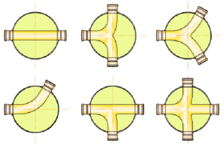
In terms of their functional and design features, they are practically similar to revision ones. The only difference between them is that the turn signal is installed in places where the pipeline bends.
The distance between the turning shafts depends on the network configuration. The indicator is calculated based on the length of straight sections between pipe bends. If it goes out longer than the norm specified for observation structures, it will be necessary to install an additional revision so that this sewer section can be monitored.
Drop wells
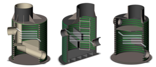
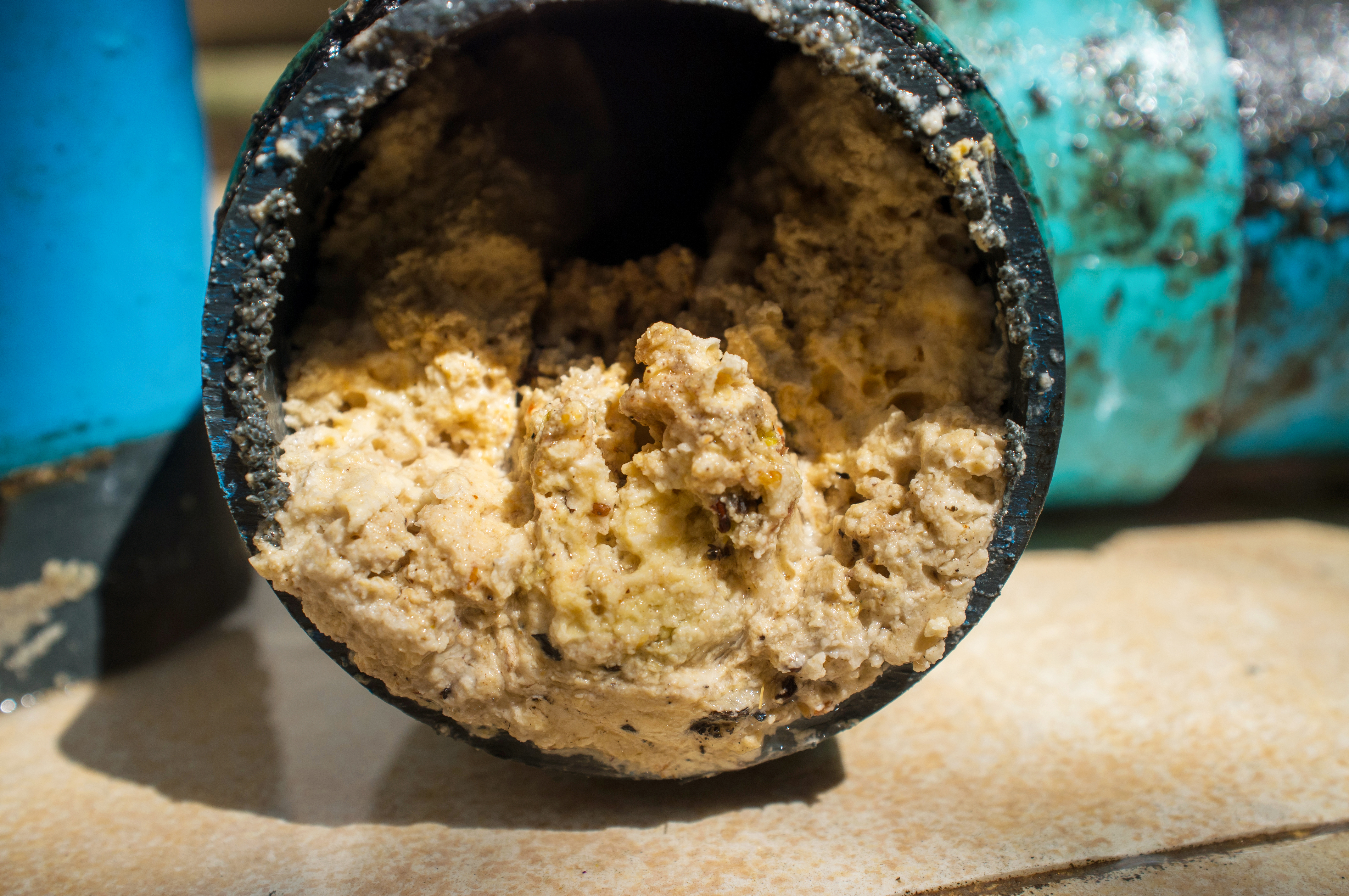
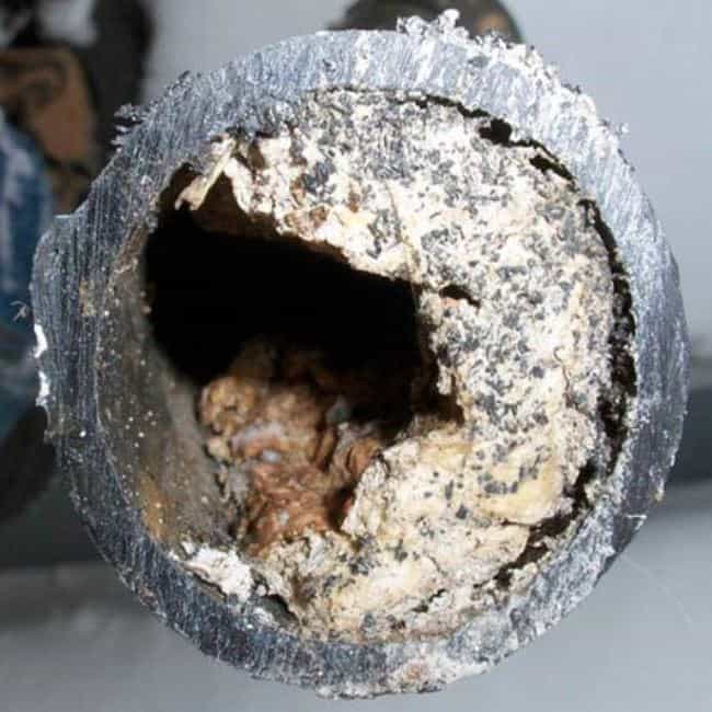
If the territory where the sewage system is being built has a complex relief, drop shafts are used. In hilly areas, the slope of the pipeline will be large. This threatens that the flow rate of wastewater will increase, solid fractions will begin to adhere to the inner surface of the pipes and, over time, create a plug. Differential shafts reduce the rate of flow of drains.
The exact standards for such structures have not been calculated; other requirements are imposed on them:
- the altitude indicator of the difference should not be more than three meters;
- at a depth of up to half a meter, the structure can be replaced with an overflow revision;
- devices are mounted in places of branch pipe bends.
At the beginning of the line, a reservoir is mounted for flushing the network in a section of low flow. It can be a revision or a special device.
Nodal mines
The reservoirs are equipped where the supplying sewer branches converge into a single drainage line. There are no regulatory requirements for them, except for the section of the mine itself:
| Diameter (mm) | |
| Pipeline | Nodal structure |
| 600 | 100 |
| 700 | 1250 |
| 800–1000 | 1500 |
| 1200–2000 | 2000 |
There can be no more than one incoming and three outgoing pipes in the chute of a structure.
Distance between storm water inlets
When creating a storm sewer on a site, it is important to take into account the distance between storm inlets. It depends on the slope of the tray and the terrain:
| General slope | Maximum distance (m) |
| Up to 0.004 | 50 |
| Up to 0.006 | 60 |
| Up to 0.01 | 70 |
| Up to 0.03 | 80 |
If the area is wider than 30 m, the distance between the storm inlets is no more than 60 m. The length from the storm inlet to the collector revision is a maximum of 40 m, and no more than one intermediate device can be installed. The cross-section of the connecting section is determined by the calculated inflow of water to the storm inlet with a slope of 0.02, but it cannot be less than 20 cm.
How to calculate a suitable distance
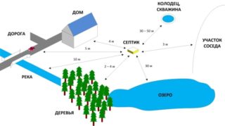
In design calculations, when creating a sewage main, the following factors are taken into account:
- relief of the territory;
- characteristic features of the soil;
- location of aquifers and sanitary protection zones;
- the presence of buildings and communication wiring.
The standards indicate the distances between structures located on straight lines. On pipelines with bends, they can slightly change in the direction of decrease. However, it is impossible to deviate greatly from the requirements, this will worsen the work of the sewage system.
In addition to the distances between the wells, other distances are taken into account. They are also important for system performance and security. For example, the minimum distance from any sewer shaft to the foundation of the house is three meters, and the maximum is twelve meters.
At least 30 meters are left between the sewage disposal devices and the water supply source so that the drains do not pollute the drinking water. The site where the water supply is installed is located 50 meters or more away from the septic tank.
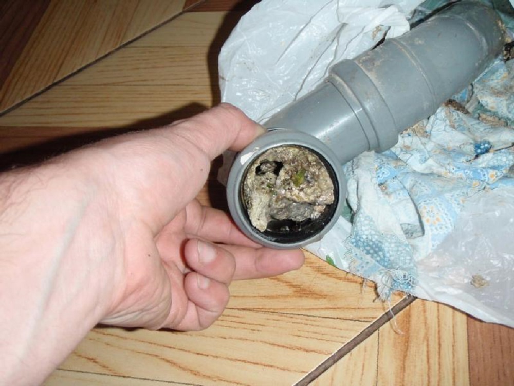
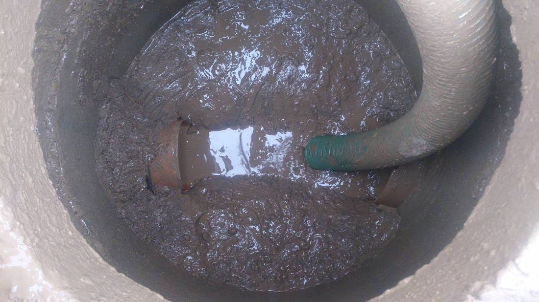
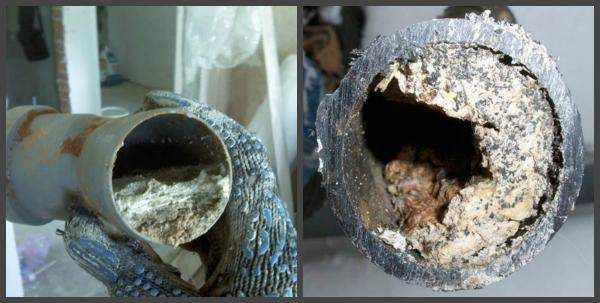
Compliance with the standards will ensure the smooth operation of the sewer system. If you ignore them, sewage lines will constantly fail, become clogged, and it will be more difficult to repair and maintain them. Correct installation of well structures will prevent potential troubles and provide access to all elements of the pipeline.

