Automation for a wicket or gate is a useful addition to their functionality. The mechanism consists of an electric roller system. The drive power depends on the weight of the web. The opening of the structure is equipped with photosensors for more efficient work. The owners of plots and garages make and install a drive for sliding gates with their own hands in order to save money.
General design of the gate mechanism
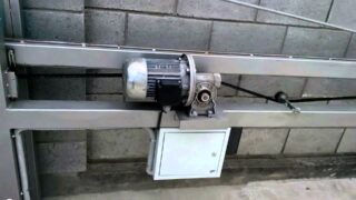
Sliding canvases work on rollers or rails, both models are distinguished by the method of technical arrangement. To move the sliding sash, a strip is released along the fence, the relief in this place should be even. At higher elevations, the mechanism experiences additional efforts and fails.
The automatic opening device includes a system of bearing girders and hinges, mechanisms are stationary and on moving wheels. Efficiency is provided by two roller devices that move along a beam of a certain section. The sliding roller system is a budget option, but requires the installation of a foundation under the guide rail and the use of a bearing system.
Console structures do not have a second rail, the sash is hung on a retractable beam. When opening, the canvas is 10 cm from the ground, which allows unhindered movement. On the cantilever run, a toothed rack with end elements is placed to adjust the opening of the door leaf.
End accessories exclude an accidental blow of the sash on a passing person or a passing car in the aisle. The wicket is often combined with the curtain, and is also equipped with automation. In the absence of electricity, it is possible to unlock the system for manual opening of the gate leaf.
Drive system design
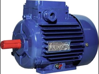
The drive for sliding gates can be hydraulic or electromechanical, but in both cases there is an electric motor in its structure. The motor communicates movement to hydraulics or mechanics. According to the power of the unit, the devices are divided into industrial and household. In private households, electric motors of 220 V are used with a repetitive intensity of action in the range of 30 - 50%. These parameters protect the motor windings from overheating.
For industrial doors made of heavy materials, heat-resistant 220 or 380V units are installed. The use of motors operating on 12V is limited due to the complex control, which leads to an increase in the cost of automation in general.
The opening mechanism includes devices:
- electric motor with a starter;
- a device that lowers the speed;
- gear pair wheel-pinion;
- working gearbox (progressive-return mechanism, connecting rod-crank unit, hydraulic cylinder pump).
The drive device contains a compensation block in the design to reduce the load on the heavy gate leaf. It can be represented by a counterweight system, torsion springs.
Functionality is increased by regular lubrication of moving parts. The tool is selected according to the working conditions, the viscosity of the composition, resistance to temperature changes and the effects of frost.The most commonly used mineral oils, traditional for our country, their mixtures with kerosene, diesel fuel, water, emulsions or expensive synthetic lubricants.
Engine selection
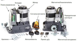
The discrepancy between the power of the motor and the mass of the web leads to a violation of the opening, the appearance of squeaks and failure.
When choosing a unit, the following criteria are taken into account:
- Weight of the structure. Automation is distinguished by torque and tractive effort. The sales documents must indicate the engine power, and not only the recommended blade weight. The motor is chosen with a margin of safety.
- Work intensity. The parameter shows the time during which the automation works continuously without failure (up to 50%). For a residential gate, this means that after 1 hour of operation, a break of 30 minutes is required.
- Opening speed. The parameter means how long it is necessary to wait for the sash to retract in order to free the opening for passage. Accelerated opening increases the load on the mechanism, so you need to pay attention to this parameter when choosing.
The quality of the automatic adaptation plays a role. It is better to purchase devices from European or Russian manufacturers. Chinese automation also has quality samples, but there is a risk of running into handicraft manufacturers.
Making the main units yourself
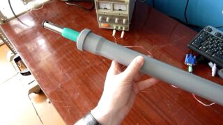
Before making an electric drive for sliding gates yourself, perform a drawing or sketch.
Homemade drives are made using improvised assemblies, car parts and household appliances:
- geared electric motors with a force over 120 N;
- glass lifters by car;
- screw jacks;
- pieces of square pipe;
- two actuators (translational devices) of the satellite dish.
Remote control is organized using a simple car alarm, while using a 12V relay to connect the motor. In addition, you need a signal lamp, wires, end switches.
The type of mechanism is determined by the distance from the web to the outer edge of the support:
- more than 15 cm - lever;
- up to 15 cm - linear.
The cover, gears and handle are removed from the jack. Grinder cut off the platform of the lift. Disassemble the window lifter, take out the motor and gearbox. A sleeve is made from a square pipe (20 x 20 mm), attached to the jack screw.
A screwdriver is used to drill holes in a bar 18 x 18 cm, where then a screw thread is cut for the gear shaft. The counterpart of the clutch is installed on the power window motor. Holes are made in the corners corresponding to those on the body. The screw part and the motor are connected with studs with nuts.
Key recommendations
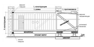
In the manufacture of the drive, not only the weight of the blade is taken into account, but also the wind load. If you do not take into account the squaring of the sash, the motor will not last long. Wind forces for the calculation are taken in the range of 50 kg per 1 square meter of the gate plane. The drive is calculated so that the power is obtained with a margin of 20 - 30% more.
If a lever device is suitable for automation, use the GAZ machine window lifters, which are combined with two levers, or take a suitable hydraulic reducer. To operate in a 220V network, a step-down transformer is installed together with a voltage converter for 12V.
Limit switches block the operation of the electric motor in the end positions, while using electrical circuits from real structures for reverse starting the engine. All the nuances of the assembly of automation are thought out in advance.
Chain Drive Assembly
Before installation, check for the presence of a warning lamp, the purchase of which should not be abandoned in order to save money. Thrift in this regard is not justified, since it increases the risk of danger to people.
Step-by-step instruction:
- Installation of the drive. It is attached to the base, which is included in the kit, then the structure is placed between the carriages.Determine the location of the rack in the center of the gear. The engine is secured with nuts.
- Installing the rail. With the gate open, the rail is welded to the leaf so that there is room for the end switches on it. The drive is unlocked. The sash is moved 1 m, the gears are connected and the second gear is welded. Adjust the gap between the gears and the rack so that it runs smoothly and the blade does not knock.
Lightweight and heavy structures are coordinated so that they can be moved by hand. Sometimes this is hindered by the lack of verticality when installing the gate, or there are obstacles along the line of movement.
Wiring diagram for sliding gate drive automation
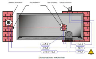
The engine is fixed before connecting the automation.
Schematic order of work:
- connection of a toothed bar and motor gears;
- introduction of end switches into operation;
- adjustment of jumpers on the control adapter;
- power on;
- setting up the remote control;
- adjustment of end relays and time;
- connection to the circuit of peripheral devices (signal lamps and photocells).
In the case of self-connecting automation, you must first assemble the circuit on the table, then transfer practical skills to real-life circumstances. It is important to choose the rules for the correct operation of the limit switches.
Mechanical end relays are bolted to prevent them from compressing the coil too much.
After the switches are triggered, the canvas travels by inertia for a few more centimeters, so the relay is adjusted so that a small gap remains as a result. The gap will protect the motor and gearbox from damage on impact.
Photocells are placed opposite each other on poles. The transmitter is connected to them with a two-wire wire, and the receiver is connected with a four-wire one. The signal lamp is connected to the terminals of the control unit so that the face is facing the road.

