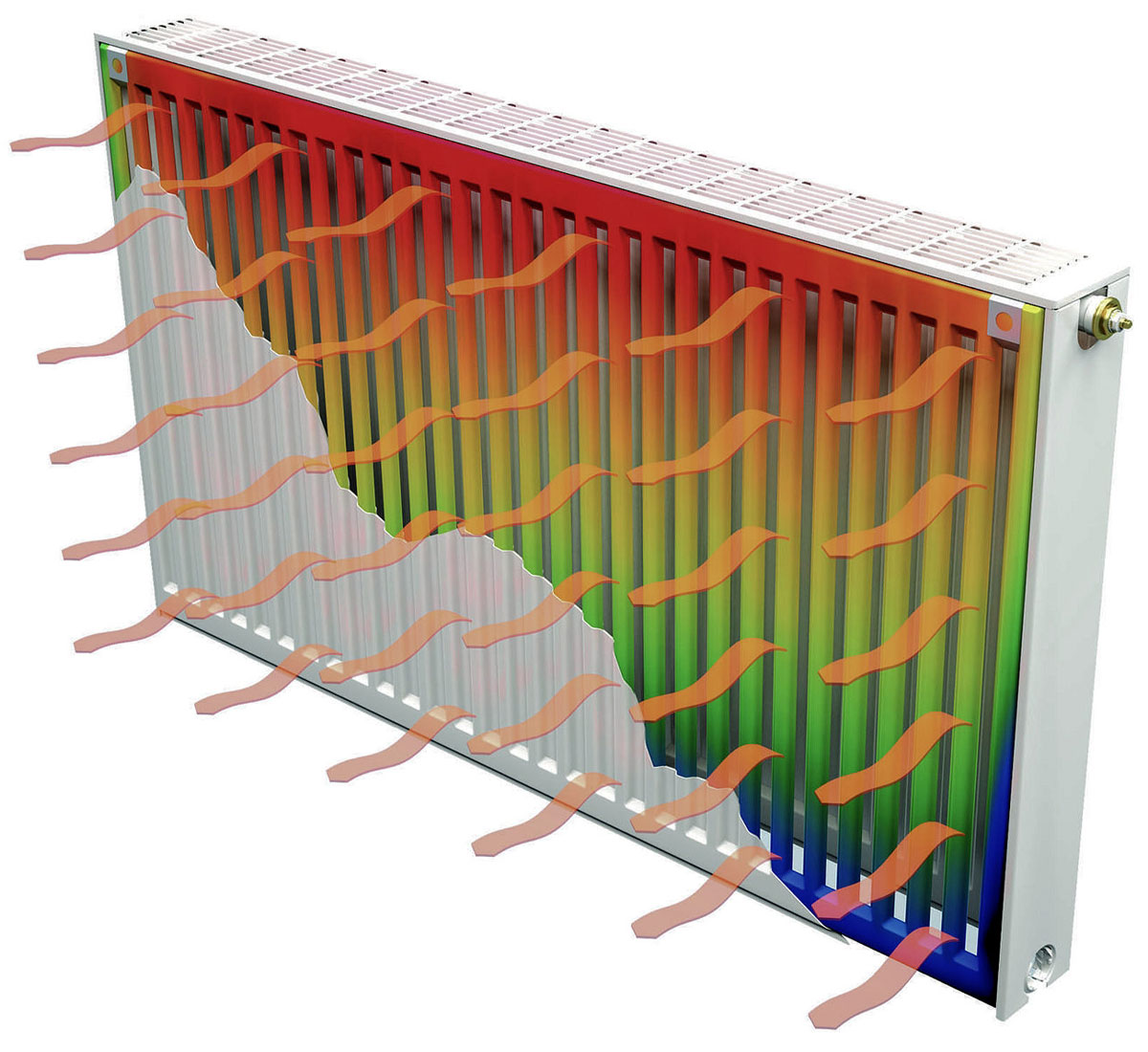
To equip a water-heated floor with your own hands, you need to deal with all the intricacies of its installation, taking into account the main characteristics of the heated building. You will need to take into account the number of rooms in the house and the total area of all its premises. Based on this, they are determined with the need for consumables, as well as with the total costs of arranging the heating system.
Laying schemes
Before starting the installation of a water heated floor, you will need to prepare a diagram indicating the location of the following working elements:
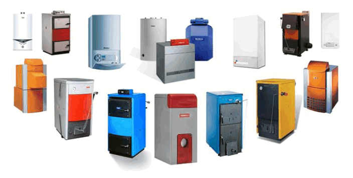
- a heating boiler - a physical source of heat;
- distribution unit - collector;
- a set of copper or polypropylene pipes that form the wiring of the heating circuit.
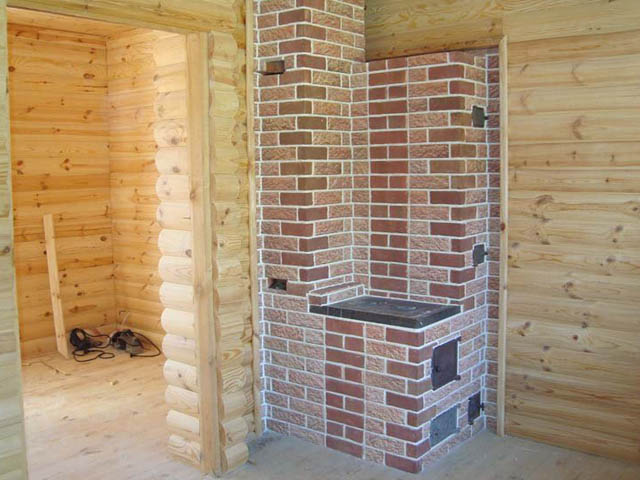
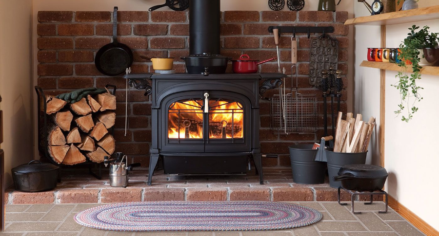
Heat sources in the house are boilers, which are kindled with solid or liquid fuel. The option of using gas equipment, which is notable for its cheapness, or its electrical counterpart, is not excluded. At the same time, the existing and operating own heating system in the house is considered as an extreme case. The manifold is usually a set of inlet and outlet fittings. The elements of the system are laid according to the following schemes:
- snake (several options);
- snail;
- according to a more complex combined scheme.
Each of the assembly operations is carried out in a special way.
Snake
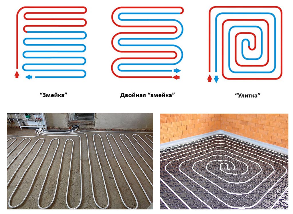
In the first version, the floor installation with a snake starts from the walls along the perimeter of the room, after which it narrows towards the center and gradually closes the usable area in the apartment. Having reached the middle, the route to be laid returns back to the boiler. Due to this, one half of the floor is warmed up during operation, and the other half is cooled. This technique allows you to evenly distribute heat during system operation.
The same result can be achieved if you start laying the snake in the form of a pipe folded in half. One half is responsible for supplying hot water, and the other, leading from the opposite wall, is used as return water.
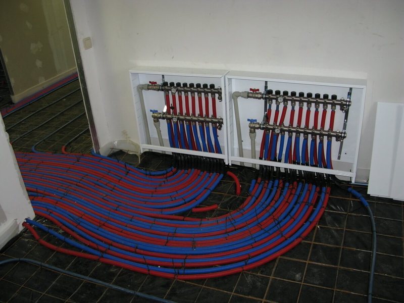
Snail
In the case of a snail, pipes folded in the same way as in a “snake” are laid along a spiral route in the form of a square structure. At first, they are carried along the walls, and then gradually move towards the center of the room. The use of this technology guarantees uniform heating of floor surfaces. Sometimes a combined scheme is used that combines elements of both of these approaches. At the same time, the areas of the floor located closer to the walls warm up more intensively, which makes it possible to reduce the boiler power while maintaining the heating intensity.
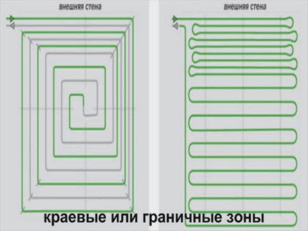
- the use of a variable pitch of pipe laying;
- displacement of the entire structure to one side;
- combination of different laying schemes.
If it is required to warm up the floor more intensively at the outer walls, the gaps between the threads in this place should be made smaller, and closer to the center, on the contrary, should be increased.
The installation diagram of a warm floor is prepared taking into account the material of the existing base. It displays the points of connection to the heat carrier source, the installation option and the removal of pipes to the walls of the room and between them.
Styling technologies
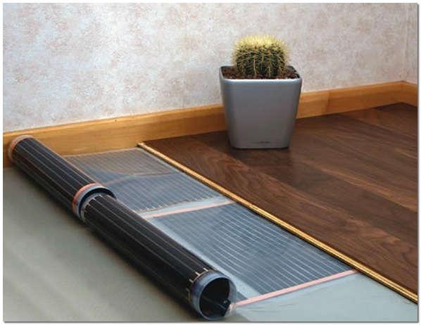
At the end of the calculation of all components of the system and the choice of a suitable scheme, they proceed to the preparation of building materials, additional equipment and tools. After that, proceed directly to the installation. Sometimes the elements of such floors are laid on polystyrene boards, placed in a certain order on a rough base. In addition, the following methods can be used for these purposes:
- placement of polypropylene pipes directly on a concrete base;
- installation of the system in the grooves of wooden plates remaining after the arrangement of the flooring;
- laying on a pre-poured screed base.
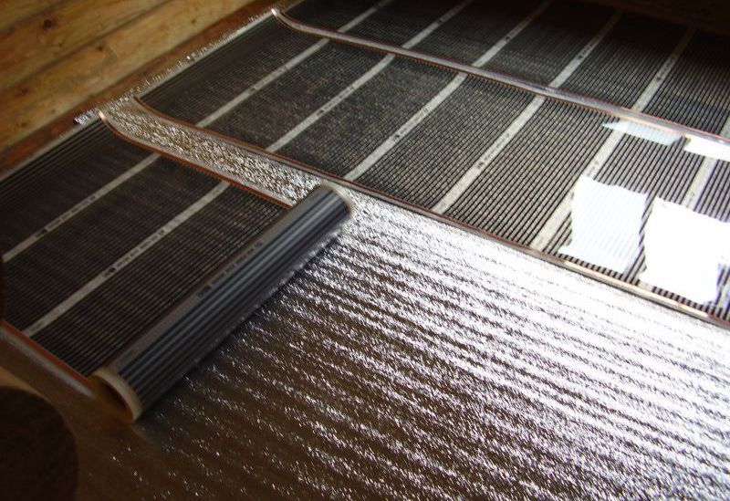
It is better to keep the heat on the plane laid on the slabs due to the use of a foil substrate, with the working side laid towards the floor. According to the instructions, during installation, the docking areas of individual elements are sealed with special tape.
Installing and connecting the collector
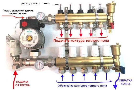
The collector, which serves to distribute the hot water carrier through the pipes of the system, is installed in a separate room or in a special distribution cabinet. It is made in the form of 2 stainless steel cylinders, welded on both sides. One of these blanks first receives through a system of pipes and then distributes the heated water along the working circuits. At the same time, the second cylinder picks up the cooled water from there, returning the carrier to the heat source.
For its circulation, a separate pump is used, supplemented by a set of bypass valves, as well as a manifold valve and thermostat. In addition to the function of distributing coolant flows, the installation of this block allows you to regulate:
- temperature of the aquatic environment by means of a thermostatic valve;
- the state of the carrier entering the heating circuit;
- its head in the system.
In the latter case, an electric actuator and a set of manifold valves are used for regulation.
Installation procedure
- Along the perimeter of the floor, edge insulation based on a damper tape is installed, which is attached to the walls of the room. In thickness, it overlaps the plane of the structure, including the insulation layer, pipes and screed with reinforced reinforcement.
- A protective foil layer is laid on the concrete floor, allowing heat to be retained in the heat insulator and concrete screed. It is placed with its protective plane towards the coating (tiles, for example).
- The joints between the individual elements are closed with foil-based tape.
- Insulation material is mounted on the insulation in the form of plates up to 50 mm thick. The rows of the heat insulator are laid with a slight offset.
- The insulation layer is closed with a steam insulator - a conventional type of polyethylene film.
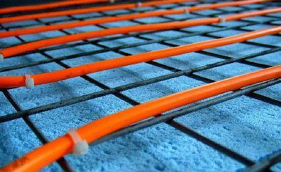
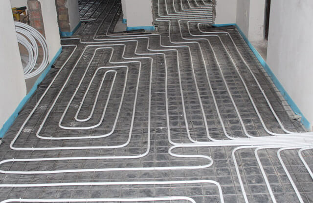
Reinforcement mesh is laid on the insulation plates with a step of 10x10 cm or 15x15 cm. It is fixed on stop brackets mounted every 0.5 meters from one another. In height, the stops are designed for the installation of 2 nets: one under the water floor, the other above it. Piping begins with the connection to the outlet of the collecting manifold.
All further operations look like this:
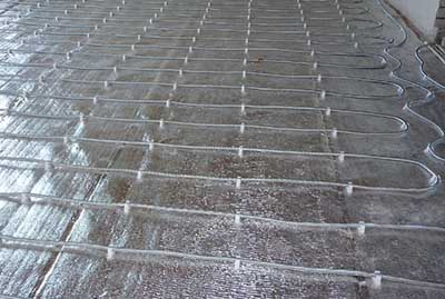
- The piping is laid along the mounted mesh, fixed to it with tightening clamps.
- The pipes themselves are not rigidly fixed on the floor, taking into account the tolerance for changing the temperature of the coolant.
- When laying polypropylene according to the "snail" scheme, the removal between the pipes is maintained within 10-15 cm - this way the heating of the floor near the walls will be better.
- If a single circuit is not enough, its area is divided into two parts with equal pipe lengths.
- Upon completion of the installation, one of the ends is connected to the manifold inlet.
- On top of the laid pipes, it is also mounted a reinforcing mesh, which gives the protective coating additional strength.
Before arranging the screed, the not yet completely finished system is tested for tightness, for which it is checked with compressed air. For this, a compressor is used that generates a pressure of 4 bar. In the presence of leaking joints, air leaves the system, and the pressure in it drops.
In addition to checking with a compressor unit, in accordance with the current regulations, hydraulic tests with hot water are mandatory. For this, a preheated liquid is fed into the system, which is then turned on for a couple of hours. If it is working properly, the pressure drops by no more than 0.03 MPa per hour.
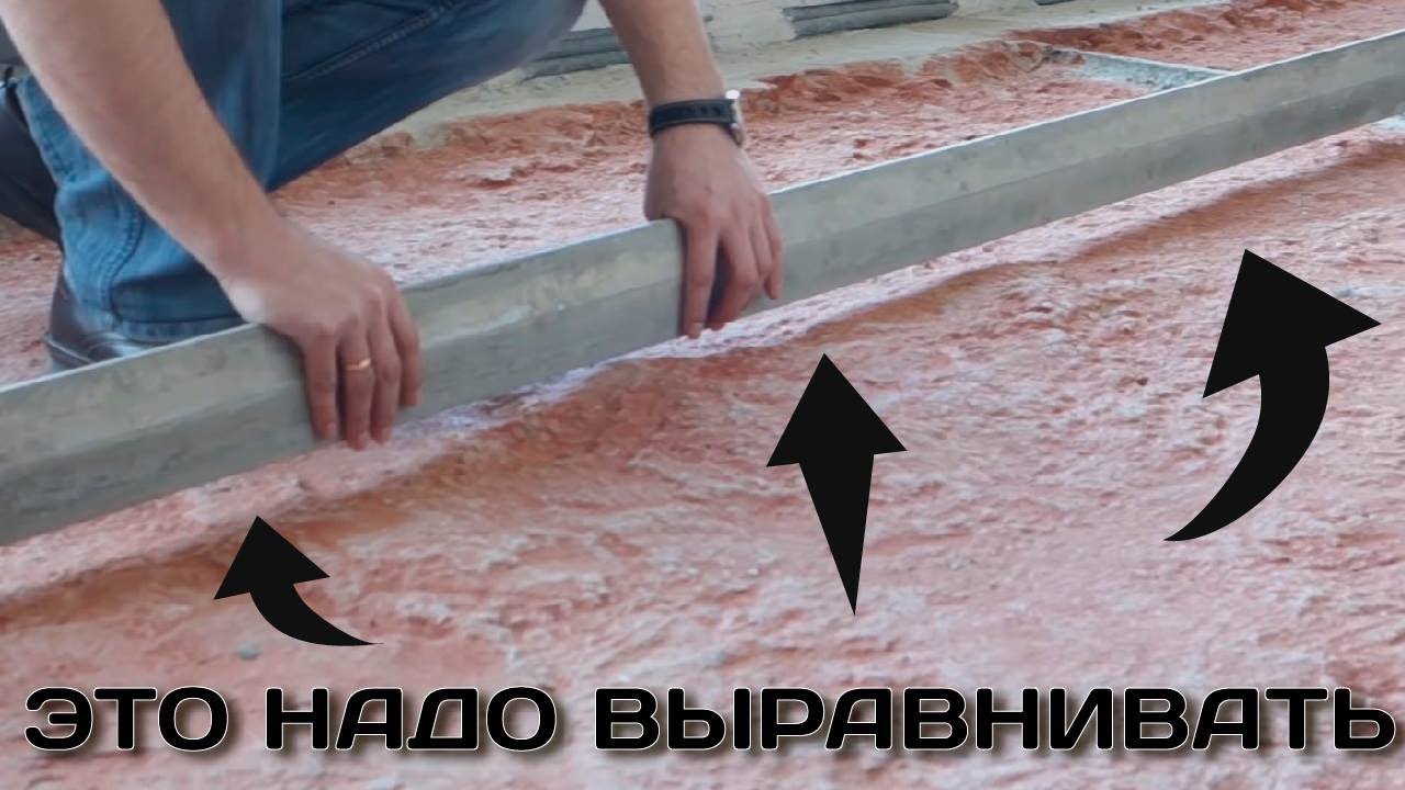
The arrangement of the concrete screed is transferred after the installation of the heated floor and the completion of the entire set of tests. Previously, polypropylene pipes are filled with cooled water pumped into them under low pressure. The screed is made with M300 concrete. The thickness of the layer covering the second reinforcing mesh is 3-5 centimeters, the total thickness of the screed is 7-10 cm. Its surface is then leveled with a vibrating screed, for which beacons are first installed. Using a vibrating tool, air is removed from the concrete and the surface is prepared for laying tiles or linoleum, for example.
It is allowed to start the formation of the floor covering 25-30 days after the concrete has cured. They dry it at a positive air temperature in the usual, natural way. When the floor area is more than 30 m2 or one wall of the room is more than 8 meters long, special shrinkage joints are used to prevent cracking of the coating. In premises of a large living area, they are arranged between individual circuits in order to pass through polypropylene pipes in areas where the comb-to-circuit transition is arranged. In the places where they are located, the pipe channels are specially protected by corrugation, and the sections of the reinforcing mesh are carefully cut.
The shrink joint is made 10 mm wide, then sealed with silicone sealant.
The correct approach to starting a warm floor includes another leak test, carried out after all work is completed. After a trial run of the system, the final decision is made on its admission to continuous operation.