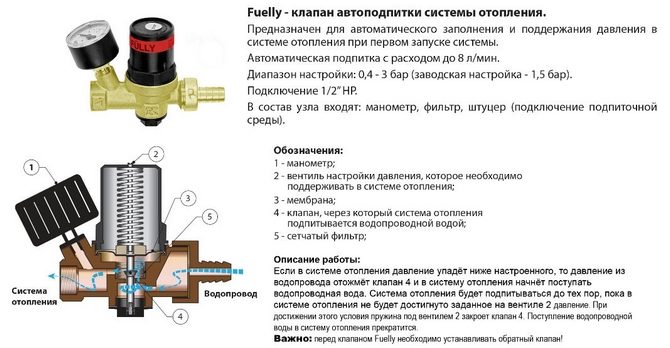
The automatic heating make-up valve is used to add liquid to the heating line. The device prevents breakdowns due to excess pressure in the circuit and water hammer. The design of the module includes a non-return valve, a pressure regulator, an auto-shut-off valve. The elements are complemented by a valve for closing control.
Purpose of the make-up valve
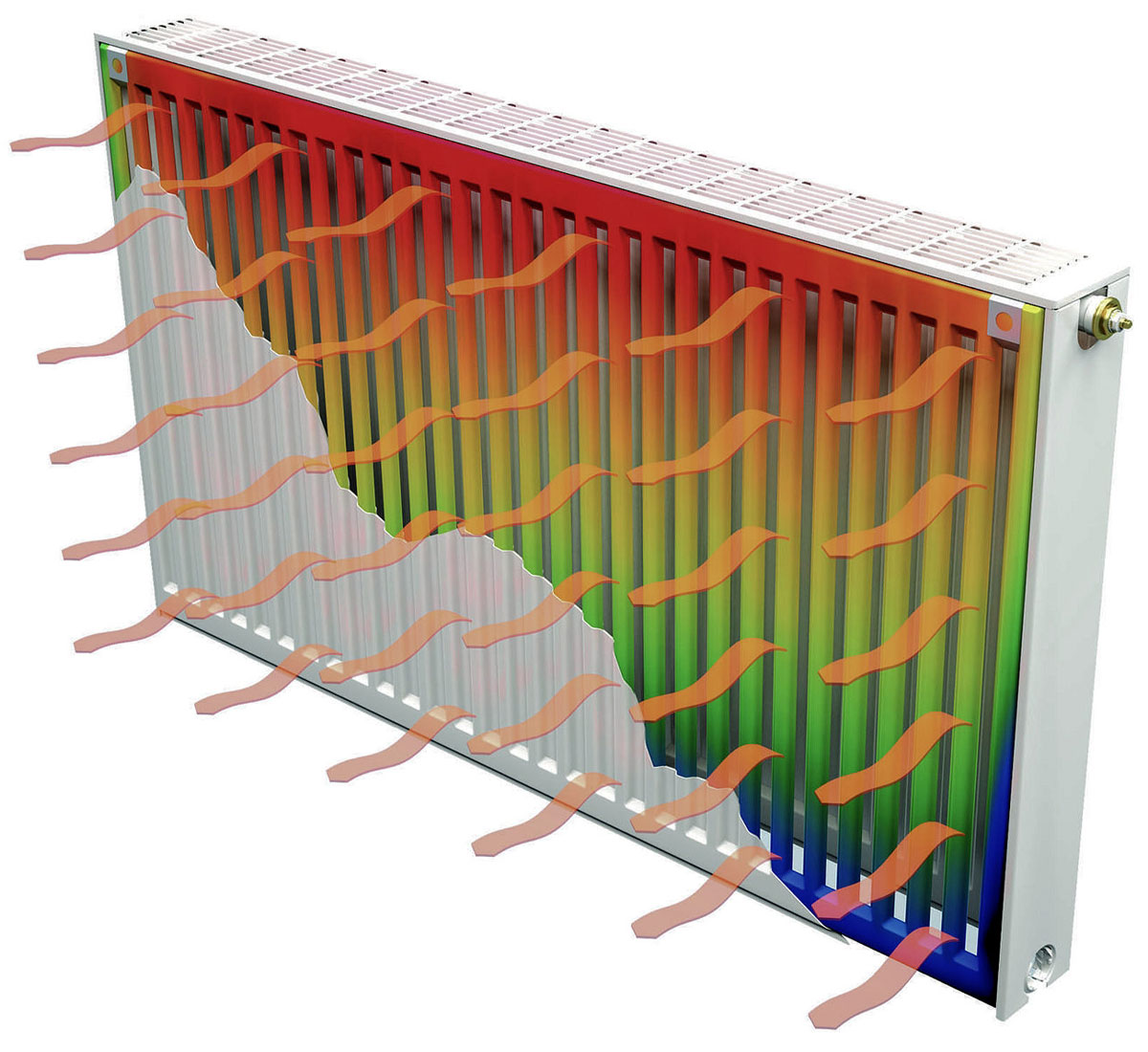
The scope of the module is autonomous heating mains of houses and structures. Regular coordination of the volume of water in the system is carried out so that when the pressure increases, leaks and deformation of pipelines do not occur. The reduced pressure of the coolant threatens to cool the radiators and underfloor heating sections.
Reasons for a decrease in water pressure:
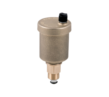
- automatic activation of air dumpers;
- natural evaporation;
- use of Mayevsky cranes;
- replacement of filters and other prophylaxis;
- activation of safety valves;
- the property of polymer pipes to expand under the influence of heat.
The filler module makes it easier to fill the system with energy. On the manometer, the working zone of the normal pressure indicator is always highlighted, and the deviation leads to blocking of the heating unit.
Valve characteristics
The automatic make-up unit maintains a uniform volume of liquid and pressure in accordance with the instructions of the boiler manufacturers.
Valve specifications:
- the highest pressure in front of the device - 10 bar;
- pressure behind the valve (adjustable) - 05 - 3 bar;
- consumption - 1.85 m3 per hour;
- sensitivity - 0.2 bar;
- maximum heating of the system - up to + 40 ° С.
The module is connected using a 1 / 2´´ diameter hose at the inlet and outlet. The pressure gauge socket has a 1 / 4´´ thread. The antifreeze pressure in the system is adjusted using a pressure gauge.
Control methods
The make-up unit assembly includes the elements:
- pressure reducer;
- pressure reducing auto valve;
- ball valve;
- bypass;
- input filter.
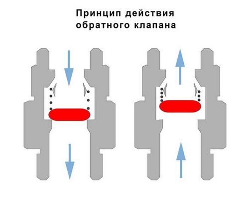
Models of make-up modules are equipped with strainers, check valves, manual cleaning elements. The non-return valve is placed behind the pressure reducing valve and serves to purify the water supply.
Automatic
Automation works according to a simple scheme and does not require external adjustment, except for the preliminary setting of parameters. The level of the lowest pressure in the system is programmed when a certain volume of water is lost.
The principle of operation consists in the automatic actuation of the valve and the start of the feed pump for heating. For the pump, the amount of water to be poured is also set, which is determined by the amount of lost energy carrier. The valve stops making up the line when the system is filled to a predetermined rate.
The pressure gauge cuts into the cold water supply pipe, sometimes a sensor for controlling the liquid pressure in two directions is used. In this place, a relay is placed, a contactor - all devices are adjusted to the operating pressure indicators.
Mechanical
The module has the ability to completely shut off or open, which is important when starting the line and filling the system with energy. A lever is provided to speed up the process. The valve is manually set to the pressure limit when it is triggered.
Make-up with mechanics is installed in small heating systems, since in them the increase in pressure is clearly determined by the position of the membrane. The lack of energy carrier in the circuit is compensated manually by simply opening the valve on the liquid supply pipe.
It is important to install a pressure gauge, the outlet to which the valves are supplied. Devices without a sensor are cheaper, but in the heating main you cannot do without it.
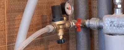
Installation features
The valve is placed on the pipe so that the direction of the liquid coincides with the direction of the arrow. The filter plug is pointing downwards and the adjustment screw must be accessible for use. The dial of the pressure gauge can be rotated for easy reading of the values.
The winding material is used rationally so that the excess does not fall into the gearbox lumen. The boiler make-up in the form of a valve should not depend on the main loads (compression, torsion, bending, vibration). For this, additional supports or expansion joints are installed.
The misalignment of the pipelines' axes should not be more than 3 mm with a length of 1 m. For a longer length, 1 mm is added for each running meter. The make-up circuit is connected to the pipeline near the expansion tank.
Make-up calculation
The calculation of the required volume of added water is carried out in accordance with SNiP 41-02-2003 "Heating networks".
In closed heating circuits, a coefficient of 0.075 is used to the total volume of the energy carrier in the networks and pipelines connected to them.
A multiplier of 0.05 is applied to the volume to calculate the make-up of sections that are more than 5 km away from the boiler room, in open and closed systems.
In open pipelines, a coefficient of 0.12 is taken to the volume of the average liquid flow rate for a hot water supply and the actual volume of the energy carrier in the pipes is added with a factor of 0.075.
Popular manufacturers
When choosing a valve, attention is paid to the assembly of the module and ease of use. The design and technical characteristics of the make-up device are taken into account. The working mechanism protects the heating system from stopping; manufacturers install filters in the structure. What matters is the operating pressure range, the permissible heating temperature of the energy carrier.
Watts
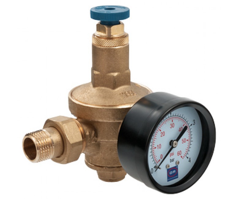
The brass body contains a check valve, a shut-off device, a coarse filter, and a screw for air relief. The inlet pressure is limited to a threshold of 10 bar and the outlet pressure is set between 0.3 and 4 bar. The bimetallic membrane is made of pressed plates with different expansion rates. The deformation of the baffle is directly proportional to the change in heating.
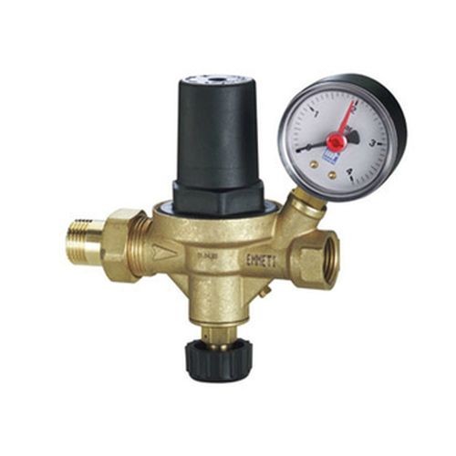
Emmeti
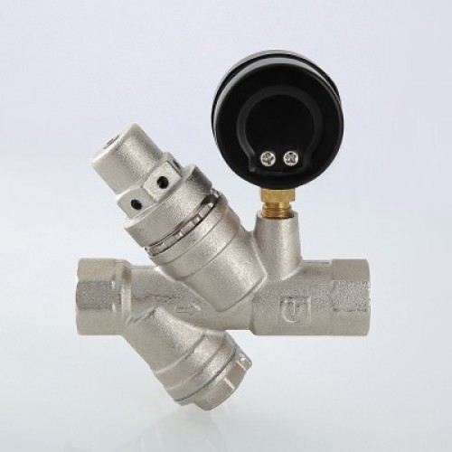
Reducing, shut-off and non-return valves are installed in the structure, the closing and opening of which is regulated by a test valve, and a socket for mounting a pressure gauge is provided. The non-return valve prevents energy carrier from entering the water supply system. The maximum consumption per hour is 1.8 m3 of liquid, the sensitivity is at the level of 0.2 bar. The maximum heating of the supply line is set to + 40 ° C, the pressure gauge is designed for a pressure of 0-4 bar.
Valtec
The body is made of brass, the springs of the check valve, the reducer and the filter mesh are made of stainless steel. The pressure gauge has accuracy class 3 and is adjustable in the range of 1 - 10 bar. Filters and pressure gauges are designed to operate in a supply line with heating up to + 130 ° C and a valve inlet pressure of 16 bar. The outlet head is selectable from 2 to 5 bar with a factory setting of 3 bar.
This thing is also called the "boiler killer". If a leak appears in the system and is not noticed - 3-6 months and any boiler will clog with deposits
It seems that the comrade explained everything correctly, helped me, and figured out all the intricacies of heating