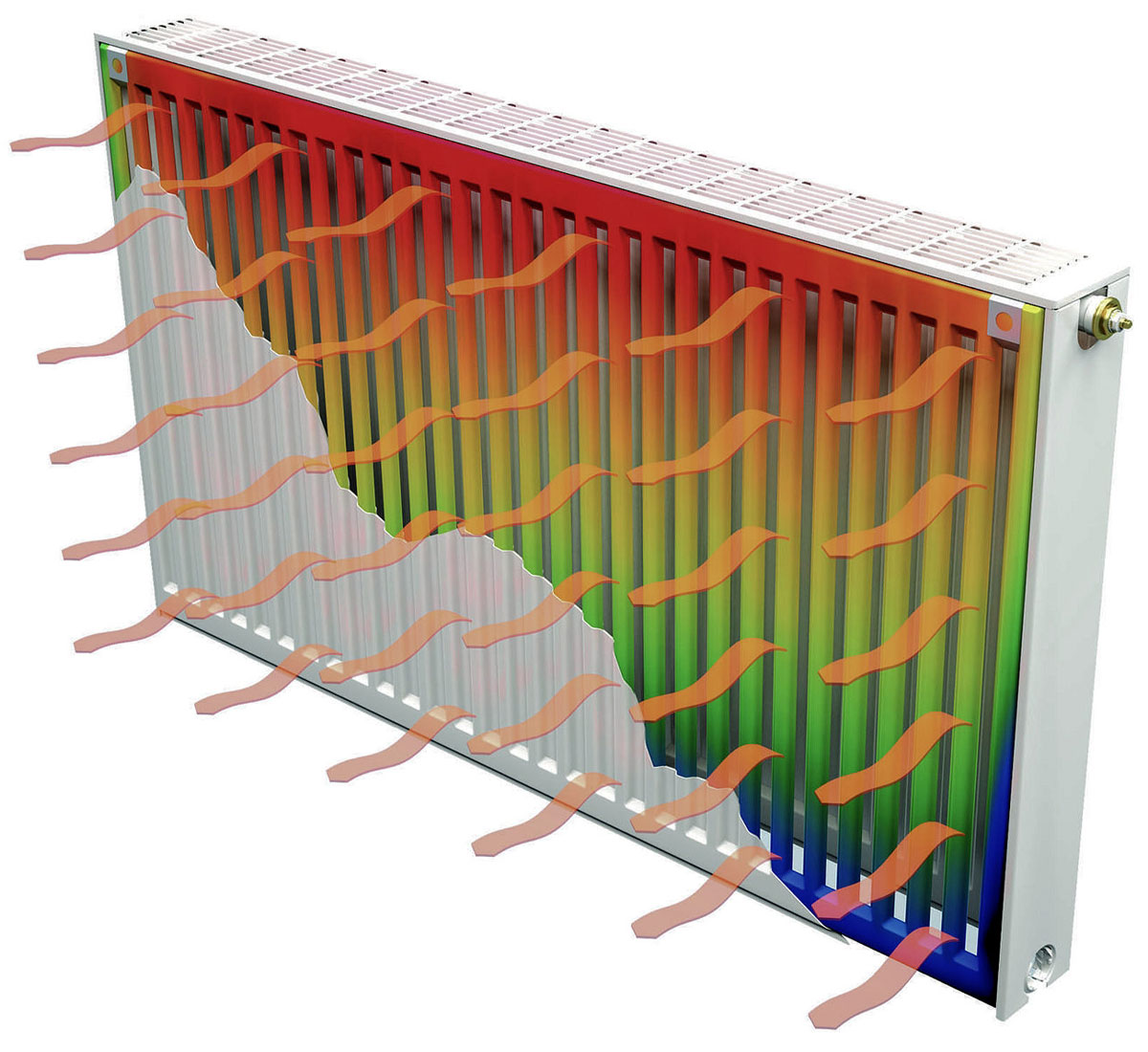
Most modern industrial and residential buildings are heated in winter by connecting to the district heating supply already connected to them. But there are often cases when independent (autonomous) sources are used to heat living spaces. With their independent installation, one cannot do without a preliminary hydraulic calculation of heating, carried out for the entire complex as a whole.
Calculation of the hydraulics of the heating ducts
The hydraulic calculation of the heating system usually comes down to the selection of the diameters of the pipes laid in separate sections of the network. When conducting it, the following factors must be taken into account:
- the value of pressure and its differences in the pipeline at a given rate of circulation of the coolant;
- its estimated expense;
- typical dimensions of the pipe products used.
When calculating the first of these parameters, it is important to take into account the capacity of the pumping equipment. It should be sufficient to overcome the hydraulic resistance of the heating circuits. In this case, the total length of polypropylene pipes is of decisive importance, with an increase in which the total hydraulic resistance of the systems as a whole increases. Based on the results of the calculation, the indicators necessary for the subsequent installation of the heating system and meeting the requirements of the current standards are determined.
Calculation of the parameters of the coolant
Calculation of the coolant is reduced to the determination of the following indicators:
- the speed of movement of water masses through the pipeline with the specified parameters;
- their average temperature;
- media consumption associated with the performance requirements of heating equipment.
When determining all the listed parameters relating directly to the coolant, the hydraulic resistance of the pipe must be taken into account. The presence of shut-off valves, which are a serious obstacle to the free movement of the carrier, is also taken into account. This point is especially important for heating systems, which include thermostatic and heat exchange devices.
The known formulas for calculating the parameters of the coolant (taking into account hydraulics) are rather complicated and inconvenient in practical use. Online calculators use a simplified approach that allows you to get a result with a margin of error for this method. Nevertheless, before starting the installation, it is important to worry about purchasing a pump with indicators not lower than the calculated ones. Only in this case there is confidence that the requirements for the system according to this criterion are fully met and that it is capable of heating the room to comfortable temperatures.
Calculation of system resistance and selection of a circulation pump
When calculating the hydraulic resistance of the heating system, the option of natural circulation of the coolant along its circuits is excluded. Only the case of forced running along the thermal circuits of a branched network of heating pipes is considered. In order for the system to operate at the specified efficiency, a sample pump is required, which in advance guarantees the required head.This value is usually represented as the volume of pumping of the coolant per selected unit of time.
To determine the total value of the resistance caused by the adhesion of water particles to the inner surfaces of pipes in the lines, the following formula is used: R = 510 4 V 1.9 / d 1.32 (Pa / m). Icon V in this ratio corresponds to the flow velocity. When carrying out independent calculations, it is always assumed that this formula is valid only for speeds not exceeding 1.25 meters / sec. If the user knows the value of the current flow rate of FWH, it is allowed to use an approximate estimate that allows to determine the internal cross-section of polypropylene pipes.
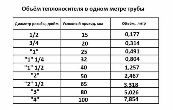
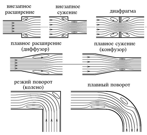
Upon completion of the basic calculations, you should refer to a special table, which indicates the approximate cross-sections of pipe passages, depending on the numbers obtained during the calculation. The most difficult and time-consuming procedure is the procedure for determining the hydraulic resistance in the following sections of the existing pipeline:
- in the areas of conjugation of its individual elements;
- in the valves serving the heating system;
- in valves and control devices.
After all the required parameters related to the performance characteristics of the coolant have been found, they proceed to the determination of all other indicators of the system.
Calculation of the volume of water and the capacity of the expansion tank
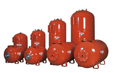
To calculate the performance of an expansion tank, which is mandatory for any closed-type heating system, you will need to deal with the phenomenon of an increase in the volume of liquid in it. This indicator is assessed taking into account changes in basic performance characteristics, including fluctuations in its temperature. In this case, it changes in a very wide range - from room +20 degrees and up to operating values in the range of 50-80 degrees.
It will be possible to calculate the volume of the expansion tank without unnecessary problems if you use a rough estimate that has been proven in practice. It is based on operating experience with equipment, according to which the volume of the expansion tank is approximately one tenth of the total amount of coolant circulating in the system. In this case, all its elements are taken into account, including heating radiators (batteries), as well as the water jacket of the boiler unit. To determine the exact value of the desired indicator, you will need to take the passport of the equipment being operated and find in it the items regarding the capacity of the batteries and the working tank of the boiler.
After determining them, it is not difficult to find excess coolant in the system. For this, the cross-sectional area of polypropylene pipes is first calculated, and then the resulting value is multiplied by the length of the pipeline. After summing up for all branches of the heating system, the numbers for the radiators and the boiler taken from the passport are added to them. One tenth is then counted from the total.
If, for example, the resulting capacity for a domestic system is about 150 liters, the estimated capacity of the expansion tank will be about 15 liters.
Determination of pressure loss in pipes
The pressure loss resistance in the circuit through which the coolant circulates is defined as their total value for all individual components. The latter include:
- loss in the primary circuit, denoted as ∆Plk;
- local costs of the heat carrier (∆Plm);
- pressure drop in special areas called "heat generators" under the designation ∆Ptg;
- losses inside the built-in heat exchange system ∆Pto.
After summing these values, the desired indicator is obtained, which characterizes the total hydraulic resistance of the system ∆Pco.
In addition to this generalized method, there are other methods for determining the head loss in polypropylene pipes. One of them is based on a comparison of two indicators tied to the beginning and end of the pipeline.In this case, the pressure loss can be calculated by simply subtracting its initial and final values, determined by two pressure gauges.
Another option for calculating the desired indicator is based on the use of a more complex formula that takes into account all the factors that affect the characteristics of the heat flow. The following ratio primarily takes into account the loss of fluid head due to the long length of the pipeline.
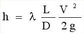
- h - liquid head loss, in the case under study, measured in meters.
- λ - coefficient of hydraulic resistance (or friction), determined by other calculation methods.
- L - the total length of the serviced pipeline, which is measured in running meters.
- D –Internal standard size of the pipe, which determines the volume of the coolant flow.
- V Is the fluid flow rate, measured in standard units (meter per second).
- Symbol g Is the acceleration of gravity, equal to 9.81 m / s2.
Losses caused by a high coefficient of hydraulic friction are of great interest. It depends on the roughness of the inner surfaces of the pipes. The ratios used in this case are valid only for standard round tube blanks. The final formula for finding them looks like this:
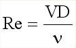
- V - the speed of movement of water masses, measured in meters / second.
- D - inner diameter defining the free space for the movement of the coolant.
- The coefficient in the denominator indicates the kinematic viscosity of the fluid.
The last indicator refers to constant values and is found in special tables, published in large quantities on the Internet.
When the flow of the coolant is accelerated, the resistance to its movement also increases. At the same time, losses in the heating network also increase, the growth of which is not proportional to the impulse that caused this effect (it changes according to the quadratic law). Hence, the conclusion follows: a high fluid flow rate in the pipeline is not beneficial both from a technical and economic point of view.