For heating private houses and summer cottages, autonomous heating installations are widely used. A common variant is with two pipes and a small generator that can run on different types of fuel. There are different schemes for a two-pipe heating system. One of the most common is the Tichelman scheme. It is characterized by stable operation and uniform heating of the radiator elements.
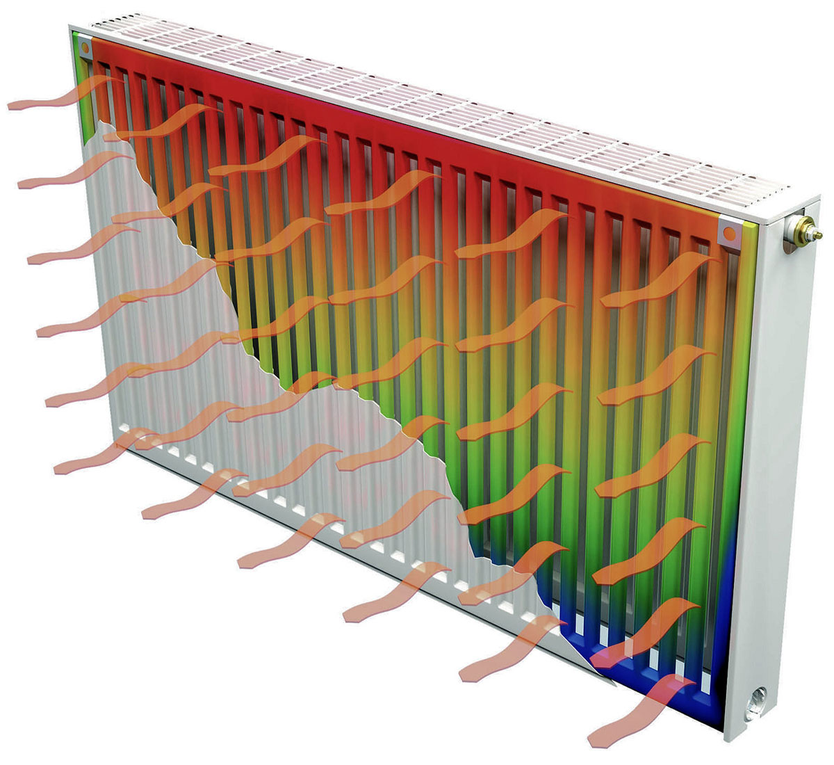
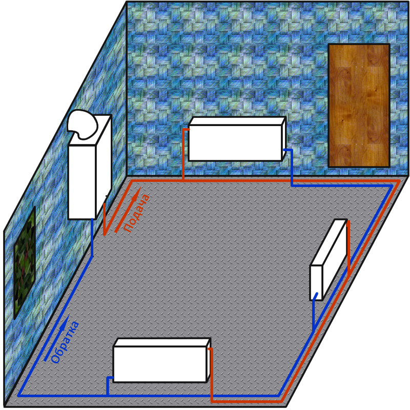
Tichelman heating scheme
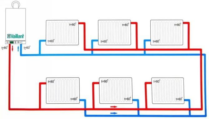
The system also has other names: it is often called passing, characterizing the movement of the heat transfer fluid along the two circuits included in it. In addition, the name of this scheme is reversed with reverse movement. One of the main features of the installation is the same length of the supply and return pipes. Since the hydraulics in different elements of the system will be identical, the end radiators receive the same amount of heat. In this case, the return flow originates from the first of them, and the feed ends at the last.
The peculiarities of the internal arrangement of one-story private houses are often such that they do not dispose of hanging heating pipes on the walls. It is usually customary to lay them under the flooring and protect them with thermal insulation. The installation of a Tichelman heating loop, in particular, a closed circle on a distribution element, is then simplified.
In rooms with high window frames, the use of floor convectors is common. When compared with a beam structure, the Tichelman heating loop is better suited for connecting these elements due to lower fuel consumption and reliability of operation.
In a two-story house, a common riser is installed and two rings are drawn for the first and second floors. It must be borne in mind that their energy losses will be very different, and select radiators and the diameters of the pipes used on this basis. The use of separate structures will allow for their mutual balancing. In a two-story house, it is convenient to place two taps in a boiler room next to each other.
Advantages and disadvantages
The advantages of installations of this type include the uniformity of heating of the entire network and the ability to adjust heat transfer by radiators. The circuit is reliable, it rarely fails, especially when compared with the operation of other systems with a large number of heating elements. This makes it a good choice for a private home.
The main drawback of the design is the limitations associated with the internal features of the arrangement of the premises. The scheme involves bypassing the perimeter of the building with a return to the boiler. In many buildings, this is not easy to organize - doors, stairwells and other obstacles do not give. Also, the installation of thicker pipes implies an increase in the cost of the configuration.
System installation process
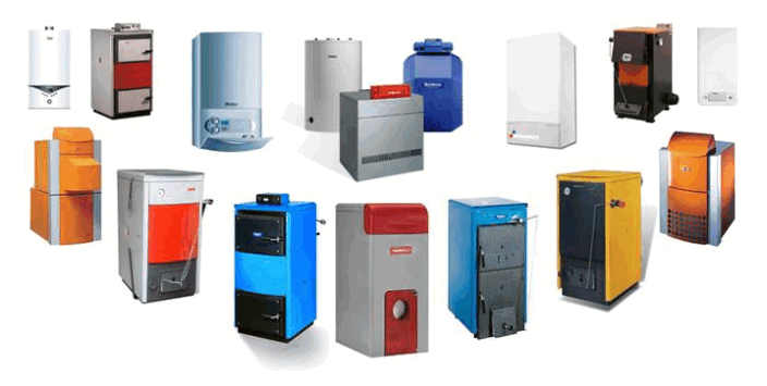
Work on the installation of Tichelman's heating begins with the installation of a boiler, which is supposed to be placed in a room of at least 250 cm. The power of the device depends on the heated area: 1000 W is required for 10 m2 of area.
After that, you need to do the following:
- Hang up the radiator sections. Having determined the required number of elements, mark their future localization - they are usually placed under the windows.Reinforce the radiators with brackets.
- Stretch pipes made of metal-plastic, through which the supply and return will go. This material is recommended for its ease of installation and high temperature resistance. Diameters should be 20-25 mm (for main pipes) and 16 mm (battery connection).
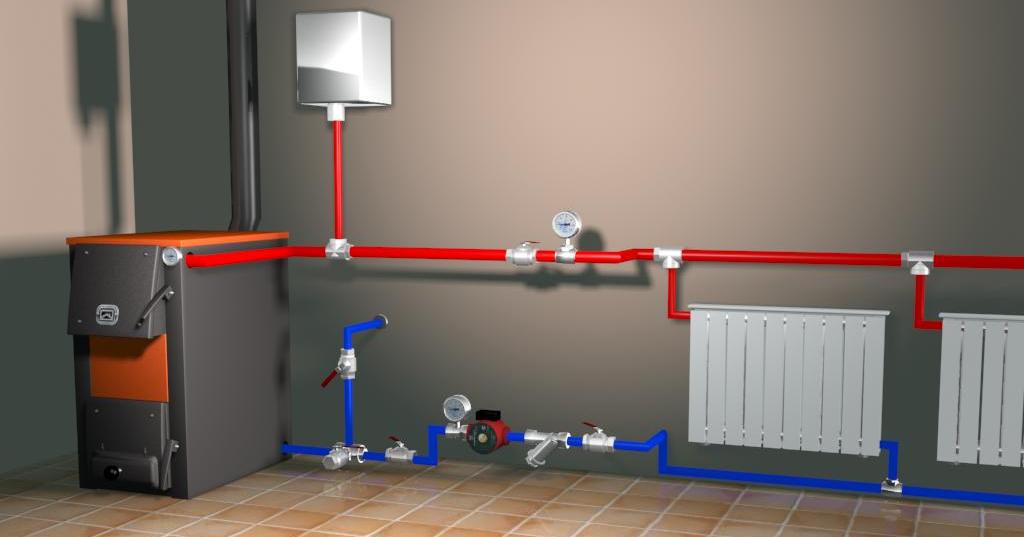
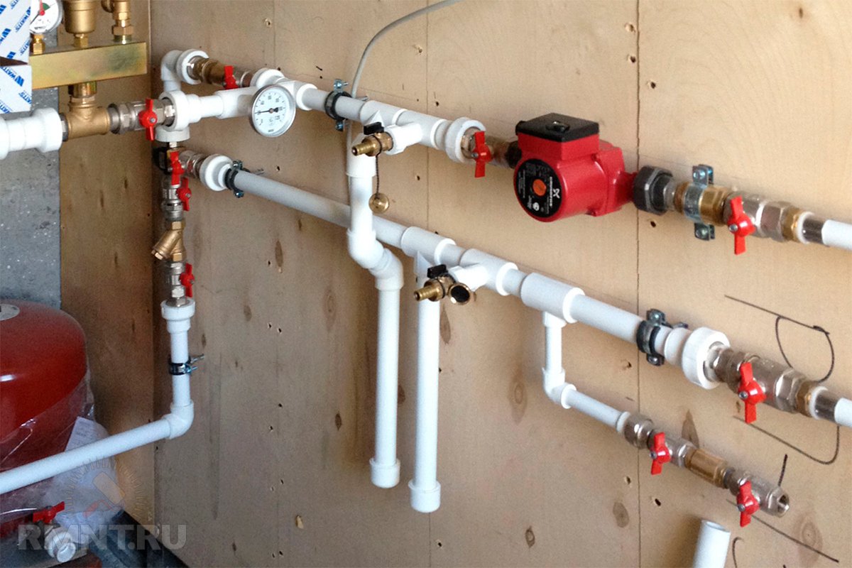
- Install the circulation pump on the return line next to the boiler. A filtration device must be placed in front of it. They cut the pump through a bypass with three taps.
- Install the expansion tank and safety parts responsible for the safety of the system.
The simplest and most inexpensive method of water preparation is the use of an indirect boiler in the Tichelman loop. Automated boilers are usually easy to connect to and control the heating device. Otherwise, to turn on the boiler, you will need to create a piping.
In ancillary and outbuildings, it is considered permissible to place a bypass pipeline directly above the doors. In this case, an air exhaust device must be placed at the highest point of the configuration, and a drainage mechanism must be installed at the bottom.
Pipes and pumps for a passing scheme
Since buildings in the private sector are characterized by a compact layout and the absence of long main routes to heating, high hydraulic resistance is not typical for such systems. To determine what diameter the pipelines should have, you can use a table describing the relationship of this parameter with the required energy.
Two-pipe system
In small rooms (150 m2 and less), heat losses do not exceed 15 kW. In this case, it is recommended to select products with an inner diameter of 2 cm and connect a 25-40 pump. In structures that heat large areas, where 15-30 kW is spent, an indicator of 25 mm is used in the main tracks. For loop configurations and branches, it is slightly reduced. To connect the radiator elements and supply to the last one, the minimum parameter value is used - 16 mm. For such an installation, a 25-60 pump is suitable.
Do-it-yourself Tichelman loop
When self-installing such a structure, you need to pay attention to the following points: the type and size of the pipes used, the selection of the capacities of the components involved and their strapping. It should also be borne in mind that a configuration with height differences (with pipe laying over the doorway) requires air venting and drainage. Sometimes, instead of arranging such an installation, they make a choice in favor of a dead-end scheme, which has a longer path length.
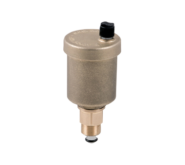
The feed contains the components responsible for the safety of the system. They include a pressure gauge, a bleed valve and an automatic air release device. The open configuration assumes vertical guidance of the track before the start of the evasion, with the expander placed at the highest point. The backbone is then routed to the remaining components of the network.
On the way back, a pump is installed, the power of which should be enough to neutralize the resistance of the hydraulics. The piping system for the boiler includes shut-off valves that are mounted next to it on both pipes and in the vicinity of the expansion tank. They are also attached to the sides of the pump and to the feed pipe located near it.
Hydraulic calculation
An important component of the circuit is the hydraulic pump, which creates supply pressure and vacuum on the return path. These calculations show that the values of both parameters decrease with increasing distance from the pump in the direction of movement of the coolant. If you measure the data on a 100-meter pipe, it turns out that at a distance of 10 m, the supply pressure will be 90% of the nominal, and the reverse vacuum will be 5%.With a range of 20 m, these parameters will be 75% and 20%, respectively, and the drop on the radiator element in both cases will be 95%. At a distance of 50-60 m, the numbers shift to the middle (45 and 40, 40 and 45, respectively), and the drop on the radiator is 85%. With further distance from the pump, the proportions continue to change in the direction of increasing vacuum; pressure reduction at a distance of 70 m will be 90%, and at a distance of 80 m and more - 95%. Thus, in the middle part, the head losses will be slightly higher than at the beginning and end. Proportionally varying indicators allow maintaining approximately equal pressure drops of the radiators.
With correct installation, no differences in the cross-section of the main pipe and the same height of the radiators, the system functions smoothly. The capacities of the batteries involved will be equal to each other.