The symbols of the water supply and sewerage system in the drawings must be indicated when designing not only multi-storey residential complexes, but also small structures. Regardless of the building features, special symbols are always used. They are regulated by GOST, they are constants and cannot be changed. UOs are also used in computer programs that create drawings.
Why is design important
Engineers equip residential buildings with systems of cold and hot supply, heating, drains, sewerage, garbage chutes, etc. To ensure that all communications work without failures, the likelihood of engineering miscalculations is minimized by the method of analysis and elimination of design errors. In order for breakdowns to be quickly calculated and eliminated, everything must be carefully planned.
The most important communications in the room are the water supply and drainage system. The design should be thought out according to a previously developed plan and implemented on the drawing. Only with the correct preparation of the project and taking into account all the requirements, a building suitable for living or working is erected.
A sewerage network is needed in all rooms and buildings to recycle waste materials and liquids. These masses are characterized by the excretion of saturated unpleasant odors, therefore, when drawing up a project, all the rules for the improvement of residential buildings, hygiene standards, etc. are taken into account. A lot of melt water, fecal matter and other household waste passes through the sewer network. All this testifies to strong loads on communications, therefore, they must be correctly designed and installed, and be reliable. However, no one is immune from force majeure, so the network is thought out in such a way that a breakdown can be quickly diagnosed and eliminated.
The drainage system guarantees comfortable living not only in large, but also in small private houses. Its main task is to discharge wastewater into special tanks. It is important that no mistakes are made during installation, otherwise wastewater will penetrate into the ground, which leads to epidemics. The water supply network also has its own individual rules and regulations.
As a rule, communication systems are designed even before the construction of buildings begins. In these cases, internal pipelines are formed, located underground. Sometimes it becomes necessary to lay a drainage system already in the finished house. Communications are mounted near structures, therefore they are called external. The solution to the problem in each case is individual, the design, respectively, is the same. The process is not easy and painstaking, so it is better to turn to a professional for drawings and projects.
There are many self-proclaimed "specialists" who do not distinguish between the symbols on the water supply diagram. Therefore, you cannot save, it is better to turn to trusted people.
Features of the image of symbols in drawings
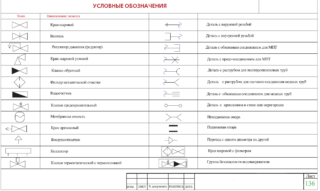
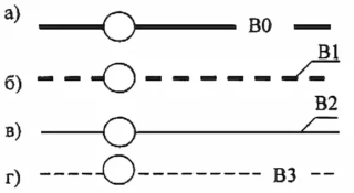
Sewer networks and water supply are schematically depicted using special geometric symbols and alphanumeric designations, and lines are also an integral part of the drawing. Symbols are not explained, exceptions are allowed only in cases where it is regulated by industry standards.
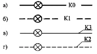
In total, at least 70 special characters are used to create drawings. Engineers, drawing up schematic sketches, use several types of lines used in drawing: straight, dotted and dotted with a dot line. In reality, they represent pipelines intended for storm water, sewage and waste water. Circular marks with the presence of a certain letter indicate the presence of a dirt, gas and grease trap, etc. in this area. In the center of the circle there is a letter by which it is easy to understand which working unit is being discussed. A circle without a letter inside indicates the presence of a sump in this place.
There are special symbols that represent plumbing items. According to GOSTs, the drawing shows toilets with different types of flushing, shower cabins equipped with a flexible hose, or bathtubs. For each individual case, there is an element that cannot be changed.
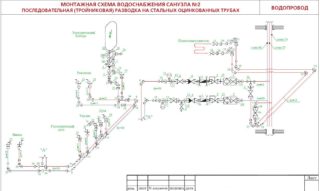
The project pays special attention to the layout plan. The drawings record the maximum amount of information that needs to be used during construction, for example, data from the table of wells, wells, specific features of the project, etc.
The water supply network is indicated by the "B" symbol. The designation of the water supply system is B0, the pipes intended for clean water are B1. Symbol B4 - water for industrial needs, is carried out, as a rule, in industries of various sizes. Sewer communications begin with the letter "K". For example, K1 is a household drainage system, K2 is used to display rainfall runoff. In industrial enterprises, the drainage network is indicated by the mark K3.
Features of graphic images on the diagram
- technical characteristics and structural features;
- location and geographic properties of the area;
- the number of structures to which communications need to be connected;
- where the waste will come from.
There are many nuances, therefore, at the initial stage, the project is developed schematically and only after all the approvals it begins to be implemented properly.
Using conventional symbols, the engineer fixes the places of input and output of communications and the location of plumbing. Depending on the type of structure, drawings can be stretched and compact. If the project is drawn up before the start of construction, all communication objects can be placed in proximity to each other, this simplifies not only the installation process, but also maintenance and repair in the future.
When it comes to the installation of communication systems in an already rebuilt house, there are many obstacles due to which communication networks have to be placed far from each other. This must be certified in the design documentation without fail.

